Devicetree Specification
Release v0.3-40-g7e1cc17
30 November 2021
1. 引言
1.1 目的和范围
各种软件组件互相配合以初始化和引导计算机系统。在将控制权传递给 OS(Operating System,操作系统) 、Bootloader(引导加载程序) 或 Hypervisor(管理程序) 等软件之前, Firmware(固件) 可能会对系统硬件执行低级初始化。Bootloader 和 Hypervisor 可以依次加载并将控制权转移给 OS。标准、一致的接口和约定有利于这些软件组件之间的交互。在本文档中,术语 引导程序(boot program) 用于泛指初始化系统状态并执行另一个软件组件(称为 客户程序(client program) )的软件组件。引导程序的示例包括:Firmware、Bootloader 和 Hypervisor。客户程序的示例包括:Bootloader、Hypervisor、OS 和专用程序。一个软件既可以是客户程序,也可以是引导程序(例如 Hypervisor)。
本规范,即设备树规范 (DTSpec,Devicetree Specification),为客户程序接口定义提供了完整的引导程序,并结合了有助于开发各种系统的最低系统要求。
本规范针对嵌入式系统的要求。嵌入式系统通常由系统硬件、操作系统和应用软件组成,这些软件是为执行一组固定的特定任务而定制的。与通用计算机不同,嵌入式系统旨在由用户使用各种软件和 I/O 设备进行定制。嵌入式系统的其他特征可能包括:
- 一组固定的 I/O 设备,其可能为应用程序高度定制
- 一块针对尺寸和成本优化的系统板
- 有限的用户接口
- 资源限制,例如有限的内存和有限的非易失性存储
- 实时性约束
- 使用多种操作系统,包括 Linux、实时操作系统,和自定义或专用的系统
本文档的组织
- 第 1 章 介绍了 DTSpec 指定的体系结构。
- 第 2 章 介绍了设备树的概念并描述了它的逻辑结构和标准属性。
- 第 3 章 规定了符合 DTSpec 的设备树所需的基本设备节点集的定义。
- 第 4 章 介绍了特定设备类别和特定设备类型的设备绑定。
- 第 5 章 规定了设备树的 DTB 编码。
- 第 6 章 规定了 DTS 源语言。
本文档中使用的约定
shall 一词用于表示为符合标准而必须严格遵守的强制性要求,不允许违背( shall 等于 is required to )。
should 一词用于表示在几种可能性中,推荐一种特别适合的,而没有提及或排除其他可能性;或者某些行为是首选但不一定是必需的;或者(以否定的形式)不赞成但不禁止某种行为( should 等于 is recommended that )。
may 一词用于表示在标准限制内允许的行为( may 等于 is permitted )。
设备树结构的示例通常以 设备树语法(Devicetree Syntax) 形式展示。有关此语法的概述,请参见 第 6 节 。
译者注:译文使用 必须 代替 shall 、 应该 代替 should 、 可以 代替 may 。
1.2 与 IEEE™ 1275 和 ePAPR 的关系
DTSpec 与 IEEE 1275 Open Firmware standard —— IEEE Standard for Boot (Initialization Configuration) Firmware: Core Requirements and Practices [IEEE1275] 松耦合。
最初的 IEEE 1275 规范及其衍生规范,例如 CHRP [CHRP] 和 PAPR [PAPR] 解决了通用计算机的问题,例如一个操作系统的单个版本如何在同一系列中的多个不同计算机上工作,以及从用户安装的 I/O 设备加载操作系统的问题。
由于嵌入式系统的性质,开放的通用计算机所面临的一些问题并不适用。DTSpec 中省略的 IEEE 1275 规范的显着特性包括:
- Plug-in device drivers
- FCode
- The programmable Open Firmware user interface based on Forth
- FCode debugging
- Operating system debugging
从 IEEE 1275 中保留的是设备树体系结构的概念,引导程序可以通过它来描述系统硬件信息并将其传达给客户程序,从而消除客户程序对系统硬件的硬编码描述的必要。
本规范部分替代了 ePAPR [EPAPR] 规范。ePAPR 记录了 Power ISA 如何使用 devicetree,涵盖了一般概念以及 Power ISA 特定的绑定。本文档的文本源自 ePAPR,但删除了特定于架构的绑定,或将它们移动到附录中。
1.3 32-bit 和 64-bit 支持
DTSpec 支持具有 32-bit 和 64-bit 寻址能力的 CPU。在适用的情况下,DTSpec 的章节描述了 32-bit 和 64-bit 寻址的任何要求或注意事项。
1.4 术语定义
AMP Asymmetric Multiprocessing. Computer available CPUs are partitioned into groups, each running a distinct operating system image. The CPUs may or may not be identical.
boot CPU The first CPU which a boot program directs to a client program’s entry point.
Book III-E Embedded Environment. Section of the Power ISA defining supervisor instructions and related facilities used in embedded Power processor implementations.
boot program Used to generically refer to a software component that initializes the system state and executes another software component referred to as a client program. Examples of a boot program include: firmware, bootloaders, and hypervisors.
client program Program that typically contains application or operating system software. Examples of a client program include: bootloaders, hypervisors, operating systems, and special purpose programs.
cell A unit of information consisting of 32 bits.
DMA Direct memory access
DTB Devicetree blob. Compact binary representation of the devicetree.
DTC Devicetree compiler. An open source tool used to create DTB files from DTS files.
DTS Devicetree syntax. A textual representation of a devicetree consumed by the DTC. See Appendix A Devicetree Source Format (version 1).
effective address Memory address as computed by processor storage access or branch instruction.
physical address Address used by the processor to access external device, typically a memory controller.
Power ISA Power Instruction Set Architecture.
interrupt specifier A property value that describes an interrupt. Typically information that specifies an interrupt number and sensitivity and triggering mechanism is included.
secondary CPU CPUs other than the boot CPU that belong to the client program are considered secondary CPUs.
SMP Symmetric multiprocessing. A computer architecture where two or more identical CPUs can share memory and IO and operate under a single operating system.
SoC System on a chip. A single computer chip integrating one or more CPU core as well as number of other peripherals.
unit address The part of a node name specifying the node’s address in the address space of the parent node.
quiescent CPU A quiescent CPU is in a state where it cannot interfere with the normal operation of other CPUs, nor can its state be affected by the normal operation of other running CPUs, except by an explicit method for enabling or re-enabling the quiescent CPU.
2. 设备树
2.1 概述
DTSpec 指定了一个称为 设备树(devicetree) 的结构来描述系统硬件。引导程序会将设备树加载到客户程序的内存中,并将指向设备树的指针传递给客户程序。
本章描述了设备树的逻辑结构,并指定了一组用于描述设备节点的基本属性。 第 3 章 指定了一个 DTSpec-compliant 的设备树所需的某些设备节点。 第 4 章 描述了 DTSpec-defined 的设备绑定(binding) —— 表示某些设备类型或设备类别的要求。 第 5 章 描述了设备树的内存编码。
设备树是一种树形数据结构,其节点描述系统中的设备。每个节点都有描述所代表设备特征的属性/值对。除了根节点之外,每个节点都有且只有一个父节点。
一个 DTSpec-compliant 的设备树描述了系统中不一定能被客户程序动态检测到的设备信息。例如,PCI 的体系结构使客户程序能够探测和检测已连接的设备,因此可能不需要描述 PCI 设备的设备树节点。但是,如果无法通过探测检测到,则需要设备节点来描述系统中的 PCI host bridge 设备。
示例
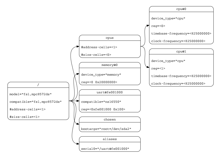
Fig. 2.1 展示了一个简单的设备树表示示例,该设备树几乎足以引导一个简单的操作系统,其中描述了平台类型、CPU、内存和单个 UART。设备节点与每个节点内的属性和值一起展示。
2.2 设备树结构和约定
2.2.1 节点名
节点命名要求
设备树中的每个节点都要根据以下约定命名:
1 | |
node-name 部分指定节点的名称。它的长度 必须 为 1 到 31 个字符,并且仅由 Table 2.1 中的字符集中的字符组成。
| Character | Description |
|---|---|
| 0-9 | digit |
| a-z | lowercase letter |
| A-Z | uppercase letter |
| , | comma |
| . | period |
| _ | underscore |
| + | plus sign |
| - | dash |
node-name 必须 以小写或大写字母开头,并应描述设备的一般类别。
unit-address 部分特定于节点所在的总线类型。它由 Table 2.1 中字符集中的一个或多个 ASCII 字符组成。unit-address 必须与节点的 reg 属性中指定的第一个地址匹配。如果节点没有 reg 属性,则必须省略 @unit-address 并且 node-name 单独将节点与树中同一级的其他节点区分开来。特定总线的绑定可以为 reg 的格式和 unit-address 指定额外的、更具体的要求。
在没有 @unit-address 的情况下,node-name 在树中同一级的任何属性名称中 必须 是唯一的。
根节点没有 node-name 或 unit-address。它由正斜杠(/)标识。
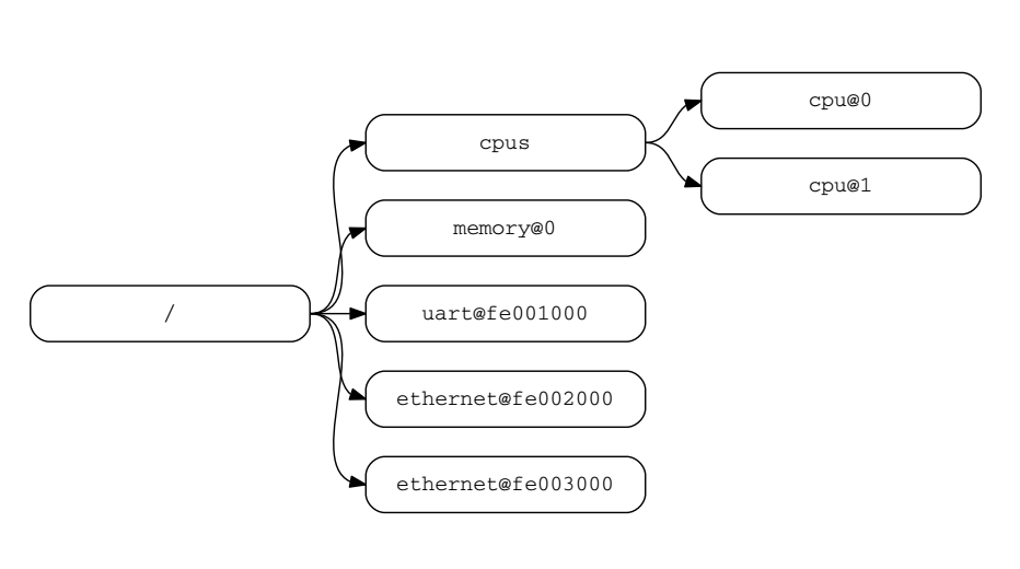
在 Fig. 2.2 中:
- 名为 cpu 的节点通过其
unit-address值 0 和 1 进行区分。 - 名为 ethernet 的节点通过其
unit-address值 fe002000 和 fe003000 进行区分。
2.2.2 通用名建议
节点的名称应该在一定程度上是通用的,它反映设备的功能,而不是其精确的编程模型。如果合适,名称应该是以下选项之一:
- adc
- accelerometer
- air-pollution-sensor
- atm
- audio-codec
- audio-controller
- backlight
- bluetooth
- bus
- cache-controller
- camera
- can
- charger
- clock
- clock-controller
- co2-sensor
- compact-flash
- cpu
- cpus
- crypto
- disk
- display
- dma-controller
- dsi
- dsp
- eeprom
- efuse
- endpoint
- ethernet
- ethernet-phy
- fdc
- flash
- gnss
- gpio
- gpu
- gyrometer
- hdmi
- hwlock
- i2c
- i2c-mux
- ide
- interrupt-controller
- iommu
- isa
- keyboard
- key
- keys
- lcd-controller
- led
- leds
- led-controller
- light-sensor
- lora
- magnetometer
- mailbox
- mdio
- memory
- memory-controller
- mmc
- mmc-slot
- mouse
- nand-controller
- nvram
- oscillator
- parallel
- pc-card
- pci
- pcie
- phy
- pinctrl
- pmic
- pmu
- port
- ports
- power-monitor
- pwm
- regulator
- reset-controller
- rng
- rtc
- sata
- scsi
- serial
- sound
- spi
- sram-controller
- ssi-controller
- syscon
- temperature-sensor
- timer
- touchscreen
- tpm
- usb
- usb-hub
- usb-phy
- video-codec
- vme
- watchdog
- wifi
2.2.3 路径名
通过指定从根节点到所有后代节点到所需节点的完整路径,可以唯一标识设备树中的节点。
指定设备路径的约定是:
1 | |
例如,在 Fig. 2.2 中,cpu #1 的设备路径是:
1 | |
根节点的路径是 /。
如果到节点的完整路径是明确的,则可以省略单元地址。
如果客户程序遇到不明确的路径,则其行为未定义。
2.2.4 属性
设备树中的每个节点都有描述节点特征的属性。属性由名称和值组成。
属性名
属性名是 Table 2.2 中展示的字符中的 1 到 31 个字符的字符串
| Character | Description |
|---|---|
| 0-9 | digit |
| a-z | lowercase letter |
| A-Z | uppercase letter |
| , | comma |
| . | period |
| _ | underscore |
| + | plus sign |
| ? | question mark |
| # | hash |
| - | dash |
非标准属性名应指定唯一的字符串前缀,例如股票代码,标识定义该属性的公司或组织的名称。例子:
1 | |
属性值
属性值是包含与属性相关信息的零个或多个字节的数组。
如果传达 true-false 信息,那么属性可能具有空值。在这种情况下,属性的存在或缺失足以描述该信息。
Table 2.3 描述了 DTSpec 定义的一组基本值类型。
| Value | Description |
|---|---|
| <empty> | Value is empty. Used for conveying true-false information, when the presence or absence of the property itself is sufficiently descriptive. |
| <u32> |
A 32-bit integer in big-endian format. Example: the 32-bit value 0x11223344 would be represented in memory as:
address 11
address+1 22
address+2 33
address+3 44
|
| <u64> |
Represents a 64-bit integer in big-endian format. Consists of two Example: the 64-bit value 0x1122334455667788 would be represented as two cells as: <0x11223344 0x55667788>. The value would be represented in memory as:
address 11
address+1 22
address+2 33
address+3 44
address+4 55
address+5 66
address+6 77
address+7 88
|
| <string> |
Strings are printable and null-terminated. Example: the string “hello” would be represented in memory as:
address 68 'h'
address+1 65 'e'
address+2 6C 'l'
address+3 6C 'l'
address+4 6F 'o'
address+5 00 '\0'
|
| <prop-encoded-array> | Format is specific to the property. See the property definition. |
| <phandle> | A <u32> value. A phandle value is a way to reference another node in the devicetree. Any node that can be referenced defines a phandle property with a unique <u32> value. That number is used for the value of properties with a phandle value type. |
| <stringlist> |
A list of <string> values concatenated together. Example: The string list “hello”,”world” would be represented in memory as:
address 68 'h'
address+1 65 'e'
address+2 6C 'l'
address+3 6C 'l'
address+4 6F 'o'
address+5 00 '\0'
address+6 77 'w'
address+7 6F 'o'
address+8 72 'r'
address+9 6C 'l'
address+10 64 'd'
address+11 00 '\0'
|
2.3 标准属性
DTSpec 为设备节点指定了一组标准属性。本节详细介绍了这些属性。由 DTSpec(见 第 3 章 )定义的设备节点可以指定有关使用标准属性的附加要求或约束。 第 4 章 描述了特定设备的表示,也可能指定附加要求。
注:本文档中的所有设备树节点示例都使用 DTS(Devicetree Source)格式来指定节点和属性。
2.3.1 compatible
属性名:compatible
值类型:<stringlist>
描述:
compatible 属性值由一个或多个定义设备特定编程模型的字符串组成。客户程序应使用此字符串列表来选择设备驱动程序。属性值由空终止字符串的串联列表组成,从特定到通用。它们允许设备表达其与一系列类似设备的兼容性,可能允许单个设备驱动程序与多个设备匹配。
推荐格式为 "manufacturer,model",其中 manufacturer 是描述制造商名称的字符串(如股票代码),model 指定型号。
compatible 字符串 应该 仅由小写字母、数字和连接符组成,并且 应该 以字母开头。单个逗号通常仅在供应商前缀之后使用。不应 使用下划线。
示例:
1 | |
在此示例中,操作系统将首先尝试查找支持 fsl,mpc8641 的设备驱动程序。如果未找到驱动程序,它将尝试找到支持更为通用的 ns16550 设备类型的驱动程序。
2.3.2 model
属性名:model
值类型:<string>
描述:
model 属性值是一个 <string>,它指定设备制造商的型号。
推荐格式为:"manufacturer,model",其中 manufacturer 是描述制造商名称的字符串(如股票代码),model 指定型号。
示例:
1 | |
2.3.3 phandle
属性名:phandle
值类型:<u32>
描述:
phandle 属性为设备树中唯一的节点指定一个数字标识符。phandle 属性值由需要引用与该属性关联的节点的其他节点使用。
示例:
参阅以下设备树摘录:
1 | |
phandle 值定义为 1。另一个设备节点可以使用 phandle 值 1 来引用 pic 节点:
1 | |
注:可能会遇到旧版本的设备树,其中包含此属性的弃用形式,称为
linux,phandle。为了兼容性,如果phandle属性不存在,客户程序可能希望支持linux,phandle。这两个属性的含义和用途是相同的。
注:DTS 中的大多数设备树(请参阅附录 A)不包含显式的
phandle属性。当 DTS 编译为二进制 DTB 格式时,DTC 工具会自动插入phandle属性。
2.3.4 status
属性名:status
值类型:<string>
描述:
status 属性表示设备的运行状态。缺少 status 属性应被视为该属性以 "okay" 值存在。有效值在 Table 2.4 中列出并定义。
| Value | Description |
|---|---|
| "okay" | Indicates the device is operational. |
| "disabled" |
Indicates that the device is not presently operational, but it might become operational in the future (for example, something is not plugged in, or switched off). Refer to the device binding for details on what disabled means for a given device. |
| "reserved" | Indicates that the device is operational, but should not be used. Typically this is used for devices that are controlled by another software component, such as platform firmware. |
| "fail" | Indicates that the device is not operational. A serious error was detected in the device, and it is unlikely to become operational without repair. |
| "fail-sss" | Indicates that the device is not operational. A serious error was detected in the device and it is unlikely to become operational without repair. The sss portion of the value is specific to the device and indicates the error condition detected. |
2.3.5 #address-cells 和 #size-cells
属性名:#address-cells, #size-cells
值类型:<u32>
描述:
#address-cells 和 #size-cells 属性可用于在设备树层次结构中具有子节点的任何设备节点,并描述应如何寻址子设备节点。 #address-cells 属性定义了用于对子节点的 reg 属性中的 address 字段进行编码的 <u32> cell 的数量。 #size-cells 属性定义了用于对子节点的 reg 属性中的 size 字段进行编码的 <u32> cell 的数量。
#address-cells 和 #size-cells 属性不是从设备树中的祖先那里继承的。它们 必须 被明确定义。
一个 DTSpec-compliant 的引导程序 必须 在所有具有子节点的节点上提供 #address-cells 和 #size-cells 。
如果缺失,客户程序 应该 假定 #address-cells 的默认值为 2,#size-cells 的默认值为 1。
示例:
参阅以下设备树摘录:
1 | |
在此示例中,soc 节点的 #address-cells 和 #size-cells 属性均设置为 1。此设置指定表示子节点的 address 和 size 各需一个 cell。
serial 设备 reg 属性必须遵循父节点(soc)中所设置的规定 —— address 由单个 cell 表示(0x4600),size 由单个 cell 表示(0x100)。
2.3.6 reg
属性名:reg
值类型:<prop-encoded-array> encoded as an arbitrary number of (address, length) pairs.
描述:
reg 属性描述了设备资源在其父总线定义的地址空间内的地址。最常见的含义是内存映射 IO 寄存器块的偏移量和长度,但在某些总线类型上可能有不同的含义。根节点定义的地址空间中的地址是 CPU 真实地址。
该值是一个 <prop-encoded-array>,由任意数量的地址和长度对组成,<address length>。 address 和 length 所需的 <u32> cell 数量特定于总线,由设备节点的父节点中的 #address-cells 和 #size-cells 属性指定。如果父节点为 #size-cells 指定值为 0,则 reg 值中的长度字段 必须 省略。
示例:
假设片上系统中的一个设备有两个寄存器块,一个 32-byte 块在 SOC 中的偏移量 0x3000 处,一个 256-byte 块在偏移量 0xFE00 处。reg 属性将编码如下(假设 #address-cells 和 #size-cells 值为 1):
1 | |
2.3.7 virtual-reg
属性名:virtual-reg
值类型:<u32>
描述:
virtual-reg 属性指定映射到设备节点的 reg 属性中指定的第一个物理地址的有效地址。此属性使引导程序能够为客户程序提供已设置的虚拟到物理映射。
2.3.8 ranges
属性名:ranges
值类型:<empty> or <prop-encoded-array> encoded as an arbitrary number of (child-bus-address, parent-bus-address, length) triplets.
描述:
ranges 属性提供了一种定义总线地址空间(子地址空间)和总线节点父节点地址空间(父地址空间)之间的映射或转换的方法。
ranges 属性值的格式是任意数量的 (child-bus-address, parent-bus-address, length) 三元组
child-bus-address是子总线地址空间内的物理地址。表示地址的 cell 数量由总线确定,可以从该节点(ranges属性所在的节点)的#address-cells确定。parent-bus-address是父总线地址空间内的物理地址。表示地址的 cell 数量由总线确定,可以从定义父地址空间的节点的#address-cells属性确定。length指定子地址空间中范围的大小。表示大小的 cell 数量可以从该节点(ranges属性所在的节点)的#size-cells确定。
如果该属性使用 <empty> 值定义,则它指定父地址空间和子地址空间相同,并且不需要地址转换。
如果该属性不存在于总线节点中,则假定该节点的子节点与父地址空间之间不存在映射。
地址翻译示例:
1 | |
soc 节点指定 ranges 属性:
1 | |
此属性值指定对于 1024 KB 范围的地址空间,子节点的物理地址 0x0 映射到父地址的物理地址 0xe0000000。使用此映射,serial 设备节点可以通过 load 或 store 地址 0xe0004600(偏移量为 0x4600(在 reg 中指定)加上在 ranges 中指定的 0xe0000000)来寻址。
2.3.9 dma-ranges
属性名:dma-ranges
值类型:<empty> or <prop-encoded-array> encoded as an arbitrary number of (child-bus-address, parent-bus-address, length) triplets.
描述:
dma-ranges 属性用于描述内存映射总线的 DMA(Direct Memory Access)结构,其设备树父级可以从源自总线的 DMA 操作访问。它提供了一种定义总线物理地址空间与总线父物理地址空间之间的映射或转换的方法。
dma-ranges 属性值的格式是任意数量的 (child-bus-address, parent-bus-address, length) 三元组。每个三元组描述一个连续的 DMA 地址范围。
child-bus-address是子总线地址空间内的物理地址。表示地址的 cell 数量由总线确定,可以从该节点(dma-ranges属性所在的节点)的#address-cells确定。parent-bus-address是父总线地址空间内的物理地址。表示地址的 cell 数量由总线确定,可以从定义父地址空间的节点的#address-cells属性确定。length指定子地址空间中范围的大小。表示大小的 cell 数量可以从该节点(dma-ranges属性所在的节点)的#size-cells确定。
2.3.10 dma-coherent
属性名:dma-coherent
值类型:<empty>
描述:
针对默认情况下 I/O 不连贯的体系结构,dma-coherent 属性用于指示设备能够进行连贯的 DMA 操作。某些体系结构默认具有连贯的 DMA,并且此属性不适用于这些体系结构。
2.3.11 name (deprecated)
属性名:name
值类型:<string>
描述:
name 属性是指定节点名称的字符串。此属性已弃用,不推荐使用。但是,它可能用于较旧的 non-DTSpec-compliant 设备树。操作系统应该根据节点名的 node-name 部分来确定节点的名称(参见 第 2.2.1 节 )。
2.3.12 device_type (deprecated)
属性名:device_type
值类型:<string>
描述:
device_type 属性在 IEEE 1275 中用于描述设备的 FCode 编程模型。由于 DTSpec 没有 FCode,因此不推荐新的应用使用该属性,并且它应该仅包含在 cpu 和 memory 节点上,以便与 IEEE 1275–derived 设备树兼容。
2.4 中断和中断映射
DTSpec 采用中断树模型来表示 Open Firmware Recommended Practice: Interrupt Mapping, Version 0.9 [b7] 中指定的中断。在设备树中存在一个逻辑中断树,它表示平台硬件中中断的层次结构和路由。虽然通常称为中断树,但从技术上讲,它是一个有向无环图(Directed Acyclic Graph)。
中断源到中断控制器的物理连接在设备树中以 interrupt-parent 属性表示。代表中断生成设备的节点包含一个 interrupt-parent 属性,该属性具有一个 phandle 值,该值指向设备的中断被路由到的设备,通常是中断控制器。如果中断生成设备没有 interrupt-parent 属性,则假定其中断父级为其设备树父级。
每个中断生成设备都包含一个 interrupts 属性,其值描述该设备的一个或多个中断源。每个源都用称为 中断说明符(Interrupt Specifier) 的信息表示。中断说明符的格式和含义特定于中断域,即其取决于其中断域根节点上的属性。中断域的根使用 #interrupt-cells 属性来定义编码中断说明符所需的 <u32> 值的数量。例如,对于 Open PIC 中断控制器,中断说明符采用两个 32-bit 值,由中断号和电平/感应信息组成。
中断域是解释中断说明符的上下文。域的根是(1)中断控制器或(2)中断联结。
- 中断控制器(Interrupt Controller) 是一个物理设备,需要一个驱动程序来处理通过它路由的中断。它也可能级联到另一个中断域。中断控制器由设备树中该节点上存在的
interrupt-controller属性指定。 - 中断联结(Interrupt Nexus) 定义了一个中断域和另一个中断域之间的转换。转换基于域特定和总线特定的信息。域之间的这种转换是使用
interrupt-map属性执行的。例如,PCI 控制器设备节点可以定义从 PCI 中断命名空间(INTA、INTB 等)到具有中断请求(IRQ,Interrupt Request)编号的中断控制器的转换的中断联结。
中断树的根是在中断树的遍历到达没有 interrupts 属性的中断控制器节点时确定的,因此没有显式的中断父节点。
参见 Fig. 2.3 中的设备树图形表示示例,其中展示了中断父关系。它展示了设备树的自然结构以及每个节点在逻辑中断树中的位置。
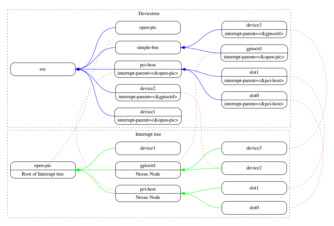
在 Fig. 2.3 所示的示例中:
- open-pic 中断控制器是中断树的根。
- 中断树根有三个子节点 —— 将它们的中断直接路由到 open-pic 的设备
- device1
- PCI host controller
- GPIO Controller
- 有三个中断域:一个植根于 open-pic 节点,一个植根于 PCI host bridge 节点,一个植根于 GPIO Controller 节点。
- 有两个联结节点:一个在 PCI host bridge 上,一个在 GPIO controller 上。
2.4.1 中断生成设备的属性
interrupts
属性名:interrupts
值类型:<prop-encoded-array> encoded as arbitrary number of interrupt specifiers
描述:
设备节点的 interrupts 属性定义设备生成的一个或多个中断。interrupts 属性的值由任意数量的中断说明符组成。中断说明符的格式由中断域根的绑定定义。
interrupts 会被 interrupts-extended 属性覆盖,通常只应使用其中一个。
示例:
在 open PIC-compatible 中断域中中断说明符的常见定义由两个 cell 组成:中断号和电平/感应信息。参见以下示例,该示例定义了一个中断说明符,中断号为 0xA,电平/感应编码为 8。
1 | |
interrupt-parent
属性名:interrupt-parent
值类型:<phandle>
描述:
由于中断树中节点的层次结构可能与设备树不匹配,因此可以使用 interrupt-parent 属性来明确定义中断父级。该值是中断父级的 phandle。如果设备中缺少此属性,则假定其中断父级为其设备树父级。
interrupts-extended
属性名:interrupts-extended
值类型:<phandle> <prop-encoded-array>
描述:
interrupts-extended 属性列出设备生成的中断。当设备连接到多个中断控制器时,应使用 interrupts-extended 代替 interrupts ,因为它使用每个中断说明符对父 phandle 进行编码。
示例:
此示例展示了具有连接到两个独立中断控制器的两个中断输出的设备如何使用 interrupts-extended 属性来描述连接。pic 是 #interrupt-cells 说明符为 2 的中断控制器,而 gic 是 #interrupts-cells 说明符为 1 的中断控制器。
1 | |
interrupts 和 interrupts-extended 属性是互斥的。设备节点 应该 只使用其中之一。只有在需要与不理解 interrupts-extended 的软件兼容时才允许同时使用两者。如果 interrupts-extended 和 interrupts 都存在,则 interrupts-extended 优先。
2.4.2 中断控制器的属性
#interrupt-cells
属性名:#interrupt-cells
值类型:<u32>
描述:
#interrupt-cells 属性定义了为中断域编码中断说明符所需的 cell 数量。
interrupt-controller
属性名:interrupt-controller
值类型:<empty>
描述:
interrupt-controller 属性的存在将节点定义为中断控制器节点。
2.4.3 中断联结属性
中断联结节点 必须 具有 #interrupt-cells 属性。
interrupt-map
属性名:interrupt-map
值类型:<prop-encoded-array> encoded as an arbitrary number of interrupt mapping entries.
描述:
interrupt-map 是联结节点上的一个属性,它将一个中断域与一组父中断域桥接,并指定子域中的中断说明符如何映射到它们各自的父域。
中断映射是一个表,其中每一行是一个映射条目,由五个部分组成:child unit address 、 child interrupt specifier 、 interrupt-parent 、 parent unit address 、 parent interrupt specifier 。
child unit address被映射的子节点的单元地址。指定这个所需的 32-bit cell 的数量由子节点所在总线节点的#address-cells属性描述。child interrupt specifier被映射的子节点的中断说明符。指定这个所需的 32-bit cell 的数量由该节点(包含interrupt-map属性的联结节点)的#interrupt-cells属性描述。interrupt-parent单个 <phandle> 值,指向子域映射到的中断父级。parent unit address中断父域中的单元地址。指定这个所需的 32-bit cell 的数量由interrupt-parent字段指向的节点的#address-cells属性描述。parent interrupt specifier父域中的中断说明符。指定这个所需的 32-bit cell 的数量由interrupt-parent字段指向的节点的#interrupt-cells属性描述。
通过将单元地址/中断说明符对与中断映射中的子部分进行匹配,在中断映射表上执行查找。因为单元中断说明符中的某些字段可能不相关,所以在查找完成之前应用掩码。此掩码在 interrupt-map-mask 属性中定义。
注:子节点和中断父节点都需要定义
#address-cells和#interrupt-cells属性。如果不需要单元地址部分,那么#address-cells必须 显式定义为零。
interrupt-map-mask
属性名:interrupt-map-mask
值类型:<prop-encoded-array> encoded as a bit mask
描述:
为中断树中的联结节点指定了 interrupt-map-mask 属性。此属性指定一个掩码,该掩码与在 interrupt-map 属性中指定的表中查找的传入单元中断说明符进行与运算。
#interrupt-cells
属性名:#interrupt-cells
值类型:<u32>
描述:
#interrupt-cells 属性定义了为中断域编码中断说明符所需的 cell 数量。
2.4.4 中断映射示例
以下展示了具有 PCI 总线控制器的设备树片段的表示和用于描述两个 PCI 槽(IDSEL 0x11,0x12)的中断路由的示例中断映射。槽 1 和 2 的 INTA、INTB、INTC 和 INTD 引脚连接到 Open PIC 中断控制器。
1 | |
一个 Open PIC 中断控制器被表示并被标识为具有 interrupt-controller 属性的中断控制器。
interrupt-map 表中的每一行由五个部分组成:子单元地址和中断说明符,它映射到具有指定父单元地址和中断说明符的 interrupt-parent 节点。
- 例如,
interrupt-map表的第一行指定槽 1 的 INTA 映射。该行组成的如下所示:
子单元地址:0x8800 0 0
子中断说明符:1
中断父级:&open-pic
父单元地址:(空,因为 open-pic 节点中#address-cells = <0>)
父中断说明符:2 1- 子单元地址为
<0x8800 0 0>。该值使用三个 32-bit cell 编码,由 PCI 控制器的#address-cells属性值(值为 3)确定。这三个 cell 代表 PCI 地址,正如 PCI 总线绑定所描述的那样。- 编码包括总线号(0x0 << 16)、设备号(0x11 << 11)和功能号(0x0 << 8)。
- 子中断说明符是
<1>,它指定了 PCI 绑定所描述的 INTA。这需要一个由 PCI 控制器的#interrupt-cells属性(值为 1)指定的 32-bit cell,它是子中断域。 - 中断父级由指向槽的中断父级的
phandle指定,即 Open PIC 中断控制器。 - 父级没有单元地址,因为父级中断域(open-pic 节点)的
#address-cells值为<0>。 - 父中断说明符是
<2 1>。表示中断说明符的 cell 数量(两个 cell)由中断父节点(open-pic 节点)上的#interrupt-cells属性确定。<2 1>的值是 Open PIC 中断控制器的设备绑定指定的值(参见 第 4.5 节 )。值<2>指定 INTA 连接到的中断控制器上的物理中断源编号。值<1>指定电平/感应编码。
- 子单元地址为
在此示例中, interrupt-map-mask 属性的值为 <0xf800 0 0 7> 。在执行查找 interrupt-map 表之前,此掩码应用于子单元中断说明符。
要查找 IDSEL 0x12(槽 2),功能 0x3 的 INTB 的 open-pic 中断源编号将执行以下步骤:
- 子单元地址和中断说明符形成值
<0x9300 0 0 2>。- 地址的编码包括总线号(0x0 << 16)、设备号(0x12 << 11)和功能号(0x3 << 8)。
- 中断说明符为 2,这是根据 PCI 绑定对 INTB 的编码。
- 应用
interrupt-map-mask值<0xf800 0 0 7>,结果为<0x9000 0 0 2>。 - 在映射到父中断说明符
<4 1>的interrupt-map表中查找该结果。
2.5 联结节点和说明符映射
2.5.1 联结节点属性
一个联结节点应该有一个 #<specifier>-cells 属性,其中 <specifier> 是一些说明符空间,例如“gpio”、“clock”、“reset”等。
<specifier>-map
属性:<specifier>-map
值类型:<prop-encoded-array> encoded as an arbitrary number of specifier mapping entries.
描述:
<specifier>-map 是联结节点中的一个属性,它将一个说明符域与一组父说明符域桥接,并描述子域中的说明符如何映射到它们各自的父域。
该映射是一个表,其中每一行都是一个映射条目,由三个部分组成: child specifier 、 specifier parent 和 parent specifier 。
child specifier是被映射的子节点的说明符。指定此部分所需的 32-bit cell 的数量由该节点(包含<specifier>-map属性的联结节点)的#<specifier>-cells属性描述。specifier parent单个 <phandle> 值,指向子域映射到的说明符父系。parent specifier父域中的说明符。指定此部分所需的 32-bit cell 的数量由说明符父节点的#<specifier>-cells属性描述。
通过将说明符与映射中的子说明符进行匹配,在映射表上执行查找。因为说明符中的某些字段可能不相关或需要修改,所以在查找完成之前应用掩码。此掩码在 <specifier>-map-mask 属性中定义(参见 第 2.5.1 节 )。
类似地,当说明符被映射时,单元说明符中的某些字段可能需要保持不变,并从子节点传递到父节点。在这种情况下,可以指定 <specifier>-map-pass-thru 属性(参见 第 2.5.1 节 )以将掩码应用于子说明符并复制与父单元说明符匹配的任何位。
<specifier>-map-mask
属性:<specifier>-map-mask
值类型:<prop-encoded-array> encoded as a bit mask
描述:
联结节点可以指定一个 <specifier>-map-mask 属性。此属性指定一个掩码,该掩码与在 <specifier>-map 属性中指定的表中查找的子单元说明符进行“与”运算。如果未指定此属性,则假定掩码是设置了所有位的掩码。
<specifier>-map-pass-thru
属性:<specifier>-map-pass-thru
值类型:<prop-encoded-array> encoded as a bit mask
描述:
联结节点可以指定一个 <specifier>-map-pass-thru 属性。此属性指定应用于在 <specifier>-map 属性中指定的表中查找的子单元说明符的掩码。子单元说明符中的任何匹配位都将复制到父说明符。如果未指定此属性,则假定掩码是未设置位的掩码。
#<specifier>-cells
属性:#<specifier>-cells
值类型:<u32>
描述:
#<specifier>-cells 属性定义了对域的说明符进行编码所需的 cell 数。
2.5.2 说明符映射示例
以下展示了具有两个 GPIO 控制器的设备树片段的表示形式和一个示例说明符映射,用于描述两个控制器上的几个 gpio 通过板上的连接器到设备的 GPIO 路由。扩展设备节点位于连接器节点的一侧,带有两个 GPIO 控制器的 SoC 位于连接器的另一侧。
1 | |
gpio-map 表中的每一行由三部分组成:一个子单元说明符,它映射到一个带有父说明符的 gpio-controller 节点。
- 例如,说明符映射表的第一行指定了连接器的 GPIO 0 的映射。该行的部分展示了:
子说明符:0 0
说明符父系:&soc_gpio1
父说明符:1 0- 子说明符是
<0 0>,它使用flags字段 0 指定连接器中的 GPIO 0。这需要连接器节点的#gpio-cells属性指定的两个 32-bit cell,它是子说明符域。 - 说明符父系由指向连接器的说明符父系(SoC 中的第一个 GPIO 控制器)的 phandle 指定。
- 父说明符是
<1 0>。表示 gpio 说明符的 cell 数量(两个 cell)由说明符父节点 soc_gpio1 上的#gpio-cells属性确定。<1 0>的值是设备绑定为 GPIO 控制器指定的值。值<1>指定连接器上的 GPIO 0 连接到的 GPIO 控制器上的 GPIO 引脚号。值<0>指定标志(低电平有效、高电平有效等)。
- 子说明符是
在此示例中, gpio-map-mask 属性的值为 <0xf 0> 。在执行查找 gpio-map 表之前,此掩码应用于子单元说明符。同样, gpio-map-pass-thru 属性的值为 <0x0 0x1> 。在将子单元说明符映射到父单元说明符时,此掩码将应用于子单元说明符。此掩码中设置的任何位都将从父单元说明符中清除,并从子单元说明符复制到父单元说明符。
要从扩展设备的 reset-gpios 属性中查找 GPIO 2 的连接器说明符源编号,将执行以下步骤:
- 子说明符形成值
<2 GPIO_ACTIVE_LOW>。- 说明符根据 GPIO 绑定使用低电平有效标志对 GPIO 2 进行编码。
gpio-map-mask值<0xf 0x0>与子说明符进行“与”运算,结果为<0x2 0>。- 在映射到父说明符
<3 0>和&soc_gpio1phandle 的gpio-map表中查找结果。 gpio-map-pass-thru值<0x0 0x1>与在gpio-map表中找到的父说明符进行反转和与运算,得到<3 0>。子说明符与gpio-map-pass-thru掩码进行“与”运算,形成<0 GPIO_ACTIVE_LOW>,然后与清除的父说明符<3 0>进行“或”运算,得到<3 GPIO_ACTIVE_LOW>。- 说明符
<3 GPIO_ACTIVE_LOW>附加到映射的 phandle&soc_gpio1中,从而产生<&soc_gpio1 3 GPIO_ACTIVE_LOW>。
3. 设备节点要求
3.1 基本设备节点类型
以下小节指定了 DTSpec-compliant 设备树中所需的基本设备节点集的要求。
所有设备树都 必须 有一个根节点,并且以下节点 必须 出现在所有设备树的根部:
- 一个 /cpus 节点
- 最少一个 /memory 节点
3.2 根节点
设备树有单个根节点,所有其他设备节点都是其后代。根节点的完整路径是 /。
| Property Name | Usage | Value Type | Definition |
|---|---|---|---|
| #address-cells | R | <u32> | Specifies the number of <u32> cells to represent the address in the reg property in children of root. |
| #size-cells | R | <u32> | Specifies the number of <u32> cells to represent the size in the reg property in children of root. |
| model | R | <string> | Specifies a string that uniquely identifies the model of the system board. The recommended format is “manufacturer,model-number”. |
| compatible | R | <stringlist> | Specifies a list of platform architectures with which this platform is compatible. This property can be used by operating systems in selecting platform specific code. The recommended form of the property value is: "manufacturer,model" For example: compatible = "fsl,mpc8572ds" |
| serial-number | O | <string> | Specifies a string representing the device's serial number. |
| chassis-type | OR | <string> |
Specifies a string that identifies the form-factor of the system. The property value can be one of:
|
| Usage legend: R=Required, O=Optional, OR=Optional but Recommended, SD=See Definition | |||
注:所有其他标准属性( 第 2.3 节 )都是允许的,但都是可选的。
3.3 /aliases 节点
设备树 可以 有一个别名节点(/aliases),它定义了一个或多个别名属性。别名节点 必须 位于设备树的根上并具有节点名称 /aliases。
/aliases 节点的每个属性都定义了一个别名。属性名称指定别名。属性值指定设备树中节点的完整路径。例如,属性 serial0 = "/simple-bus@fe000000/serial@llc500" 定义别名 serial0 。
别名 必须 为以下字符集中的 1 到 31 个字符的小写文本字符串。
| Character | Description |
|---|---|
| 0-9 | digit |
| a-z | lowercase letter |
| - | dash |
别名值是设备路径并被编码为字符串。该值表示节点的完整路径,但路径不需要引用叶节点。
客户程序可以使用别名属性名称来引用完整的设备路径作为其字符串值的全部或部分。客户程序在将字符串视为设备路径时,应检测并使用别名。
示例:
1 | |
给定别名 serial0,客户程序会查找 /aliases 节点并确定别名指的是设备路径 /simple-bus@fe000000/serial@llc500 。
3.4 /memory 节点
所有设备树都需要一个内存设备节点,它描述了系统的物理内存布局。如果系统有多个内存范围,可以创建多个内存节点,或者可以在单个内存节点的 reg 属性中指定范围。
节点名称的 unit-name 部分(参见 第 2.2.1 节 )应为 memory。
客户程序可以使用它选择的任何存储属性访问任何内存预留(参见 第 5.3 节 )未覆盖的内存。但是,在更改用于访问真实页面的存储属性之前,客户程序负责执行体系结构与实现所需的操作,可能包括从缓存中刷新真实页面。引导程序负责确保在不采取与存储属性更改相关联的任何操作的情况下,客户程序可以安全地访问所有内存(包括内存预留覆盖的内存),因为 WIMG = 0b001x。即:
- 不要求直写
- 不禁止缓存
- 内存一致性
- 需要不保护或保护
如果支持 VLE 存储属性,则 VLE=0。
| Property Name | Usage | Value Type | Definition |
|---|---|---|---|
| device_type | R | <string> | Value shall be “memory” |
| reg | R | <prop-encoded-array> | Consists of an arbitrary number of address and size pairs that specify the physical address and size of the memory ranges. |
| initial-mapped-area | O | <prop-encoded-array> | Specifies the address and size of the Initial Mapped Area Is a prop-encoded-array consisting of a triplet of (effective address, physical address, size). The effective and physical address shall each be 64-bit (<u64> value), and the size shall be 32-bits (<u32> value). |
| hotpluggable | O | <empty> | Specifies an explicit hint to the operating system that this memory may potentially be removed later. |
| Usage legend: R=Required, O=Optional, OR=Optional but Recommended, SD=See Definition | |||
注:所有其他标准属性( 第 2.3 节 )都是允许的,但都是可选的。
3.4.1 /memory 节点和 UEFI
通过 [UEFI] 引导时,系统内存映射是通过 [UEFI] § 7.2 中定义的 GetMemoryMap() UEFI 引导时服务获得的,如果存在,操作系统必须忽略任何 /memory 节点。
3.4.2 /memory 示例
给定具有以下物理内存布局的 64-bit Power 系统:
- RAM:起始地址 0x0,长度 0x80000000(2 GB)
- RAM:起始地址 0x100000000,长度 0x100000000(4 GB)
内存节点可以定义如下,假设 #address-cells = <2> 和 #size-cells = <2> 。
示例 1:
1 | |
示例 2:
1 | |
reg 属性用于定义两个内存范围的地址和大小。2 GB I/O 区域被跳过。请注意,根节点的 #address-cells 和 #size-cells 属性指定的值为 2,这意味着需要两个 32-bit cell 来定义内存节点的 reg 属性的地址和长度。
3.5 /reserved-memory 节点
Reserved memory 被指定为 /reserved-memory 节点下的一个节点。操作系统 必须 将 reserved memory 排除在正常使用之外。可以创建描述特定 reserved memory(从正常使用中排除)区域的子节点。这样的内存区域通常是为各种设备驱动程序的特殊用途而设计的。
每个内存区域的参数可以通过以下节点编码到设备树中:
3.5.1 /reserved-memory 父节点
| Property Name | Usage | Value Type | Definition |
|---|---|---|---|
| #address-cells | R | <u32> | Specifies the number of <u32> cells to represent the address in the reg property in children of root. |
| #size-cells | R | <u32> | Specifies the number of <u32> cells to represent the size in the reg property in children of root. |
| ranges | R | <prop-encoded-array> | This property represents the mapping between parent address to child address spaces (see Section 2.3.8, ranges). |
| Usage legend: R=Required, O=Optional, OR=Optional but Recommended, SD=See Definition | |||
#address-cells 和 #size-cells 应该使用与根节点相同的值,并且 ranges 应该为空,以便地址转换逻辑正常工作。
3.5.2 /reserved-memory/ 子节点
reserved-memory 节点的每个子节点指定一个或多个 reserved memory 区域。每个子节点可以使用 reg 属性来指定特定范围的 reserved memory,或者使用带有可选约束的 size 属性来请求动态分配的内存块。
按照通用名称推荐的做法,节点名称应该反映节点的用途(即“framebuffer”或“dma-pool”)。如果节点是静态分配,则应将单元地址(@<address>)附加到名称中。
Reserved memory 节点需要用于静态分配的 reg 属性或用于动态分配的 size 属性。动态分配可以使用 alignment 和 alloc-ranges 属性来限制从哪里分配内存。如果 reg 和 size 都存在,则该区域被视为静态分配,其中 reg 属性优先,并且忽略 size 。
| Property Name | Usage | Value Type | Definition |
|---|---|---|---|
| reg | O | <prop-encoded-array> | Consists of an arbitrary number of address and size pairs that specify the physical address and size of the memory ranges. |
| size | O | <prop-encoded-array> | Size in bytes of memory to reserve for dynamically allocated regions. Size of this property is based on parent node’s #size-cells property. |
| alignment | O | <prop-encoded-array> | Address boundary for alignment of allocation. Size of this property is based on parent node’s #size-cells property. |
| alloc-ranges | O | <prop-encoded-array> | Specifies regions of memory that are acceptable to allocate from. Format is (address, length pairs) tuples in same format as for reg properties. |
| compatible | O | <stringlist> |
May contain the following strings:
|
| no-map | O | <empty> | If present, indicates the operating system must not create a virtual mapping of the region as part of its standard mapping of system memory, nor permit speculative access to it under any circumstances other than under the control of the device driver using the region. |
| reusable | O | <empty> | The operating system can use the memory in this region with the limitation that the device driver(s) owning the region need to be able to reclaim it back. Typically that means that the operating system can use that region to store volatile or cached data that can be otherwise regenerated or migrated elsewhere. |
| Usage legend: R=Required, O=Optional, OR=Optional but Recommended, SD=See Definition | |||
注:所有其他标准属性( 第 2.3 节 )都是允许的,但都是可选的。
no-map 和 reusable 属性是互斥的,不能在同一个节点中同时使用。
Linux 实现注释:
- 如果存在
linux,cma-default属性,则 Linux 将使用该区域作为连续内存分配器的默认池。 - 如果存在
linux,dma-default属性,则 Linux 将使用该区域作为一致 DMA 分配器的默认池。
3.5.3 设备节点对 reserved memory 的引用
/reserved-memory 节点中的区域可以通过向设备节点添加 memory-region 属性被其他设备节点引用。
| Property Name | Usage | Value Type | Definition |
|---|---|---|---|
| memory-region | O | <prop-encoded-array> | phandle, specifier pairs to children of /reserved-memory |
| memory-region-names | O | <stringlist> | A list of names, one for each corresponding entry in the memory-region property |
| Usage legend: R=Required, O=Optional, OR=Optional but Recommended, SD=See Definition | |||
3.5.4 /reserved-memory 和 UEFI
当通过 [UEFI] 引导时,静态 /reserved-memory 区域也必须列在通过 [UEFI] § 7.2 中定义的 GetMemoryMap() UEFI 引导时服务获得的系统内存映射中。Reserved memory 区域需要包含在 UEFI 内存映射中,以防止 UEFI 应用程序进行分配。
具有 no-map 属性的保留区域必须以 EfiReservedMemoryType 类型列在内存映射中。所有其他保留区域必须以 EfiBootServicesData 类型列出。
动态 reserved memory 区域不得在 [UEFI] 内存映射中列出,因为它们是由操作系统在退出固件启动服务后分配的。
3.5.5 /reserved-memory 示例
此示例为 Linux 内核定义了 3 个连续区域:所有设备驱动程序的一个默认区域(名为 linux,cma 并且 size 为 64MiB),一个专用于帧缓冲设备(名为 framebuffer@78000000 ,8MiB),一个用于多媒体处理(名为 multimedia@77000000 ,64MiB)。
1 | |
3.6 /chosen 节点
/chosen 节点不代表系统中的真实设备,但描述了系统固件在运行时选择或指定的参数。它 必须 是根节点的子节点。
| Property Name | Usage | Value Type | Definition |
|---|---|---|---|
| bootargs | O | <string> | A string that specifies the boot arguments for the client program. The value could potentially be a null string if no boot arguments are required. |
| stdout-path | O | <string> | A string that specifies the full path to the node representing the device to be used for boot console output. If the character “:” is present in the value it terminates the path. The value may be an alias. If the stdin-path property is not specified, stdout-path should be assumed to define the input device. |
| stdin-path | O | <string> | A string that specifies the full path to the node representing the device to be used for boot console input. If the character “:” is present in the value it terminates the path. The value may be an alias. |
| Usage legend: R=Required, O=Optional, OR=Optional but Recommended, SD=See Definition | |||
注:所有其他标准属性( 第 2.3 节 )都是允许的,但都是可选的。
示例:
1 | |
可能会遇到旧版本的设备树,其中包含不推荐使用的 stdout-path 属性形式,称为 linux,stdout-path 。为了兼容性,如果 stdout-path 属性不存在,客户程序可能希望支持 linux,stdout-path 。这两个属性的含义和用途是相同的。
3.7 /cpus 节点属性
所有设备树都需要一个 /cpus 节点。它并不代表系统中的真实设备,而是充当代表系统 CPU 的子 cpu 节点的容器。
| Property Name | Usage | Value Type | Definition |
|---|---|---|---|
| #address-cells | R | <u32> | The value specifies how many cells each element of the reg property array takes in children of this node. |
| #size-cells | R | <u32> | Value shall be 0. Specifies that no size is required in the reg property in children of this node. |
| Usage legend: R=Required, O=Optional, OR=Optional but Recommended, SD=See Definition | |||
注:所有其他标准属性( 第 2.3 节 )都是允许的,但都是可选的。
/cpus 节点可能包含跨 cpu 节点通用的属性。有关详细信息,请参阅 第 3.8 节 。
示例参见 第 3.8.4 节 。
3.8 /cpus/cpu* 节点属性
一个 cpu 节点代表一个硬件执行块,它足够独立,能够运行操作系统而不干扰可能运行其他操作系统的其他 CPU。
共享 MMU 的硬件线程通常会在一个 cpu 节点下表示。如果设计了其他更复杂的 CPU 拓扑,则 CPU 的绑定必须描述拓扑(例如,线程不共享 MMU)。
CPU 和线程通过统一的编号空间进行编号,该编号空间应尽可能匹配中断控制器的 CPUs/threads 编号。
跨 cpu 节点具有相同值的属性可以放在 /cpus 节点中。客户程序必须首先检查特定的 cpu 节点,但如果未找到预期的属性,则它应该查看父 /cpus 节点。这导致在所有 CPU 中相同的属性的详细表示。
每个 CPU 节点的节点名称应为 cpu。
3.8.1 /cpus/cpu* 节点的通用属性
下表描述了 cpu 节点的通用属性。Table 3.9 中描述的一些属性是具有特定适用细节的选定标准属性。
| Property Name | Usage | Value Type | Definition |
|---|---|---|---|
| device_type | R | <string> | Value shall be "cpu". |
| reg | R | array | The value of reg is a <prop-encoded-array> that defines a unique CPU/thread id for the CPU/threads represented by the CPU node. If a CPU supports more than one thread (i.e. multiple streams of execution) the reg property is an array with 1 element per thread. The #address-cells on the /cpus node specifies how many cells each element of the array takes. Software can determine the number of threads by dividing the size of reg by the parent node’s #address-cells. If a CPU/thread can be the target of an external interrupt the reg property value must be a unique CPU/thread id that is addressable by the interrupt controller. If a CPU/thread cannot be the target of an external interrupt, then reg must be unique and out of bounds of the range addressed by the interrupt controller. If a CPU/thread’s PIR (pending interrupt register) is modifiable, a client program should modify PIR to match the reg property value. If PIR cannot be modified and the PIR value is distinct from the interrupt controller number space, the CPUs binding may define a bindingspecific representation of PIR values if desired. |
| clock-frequency | R | array |
Specifies the current clock speed of the CPU in Hertz. The value is a <prop-encoded-array> in one of two forms:
|
| timebase-frequency | R | array |
Specifies the current frequency at which the timebase and decrementer registers are updated (in Hertz). The value is a <prop-encoded-array> in one of two forms:
|
| status | SD | <string> | A standard property describing the state of a CPU. This property shall be present for nodes representing CPUs in a symmetric multiprocessing (SMP) configuration. For a CPU node the meaning of the "okay", "disabled" and "fail" values are as follows: "okay": The CPU is running. "disabled": The CPU is in a quiescent state. "fail": The CPU is not operational or does not exist. A quiescent CPU is in a state where it cannot interfere with the normal operation of other CPUs, nor can its state be affected by the normal operation of other running CPUs, except by an explicit method for enabling or reenabling the quiescent CPU (see the enablemethod property). In particular, a running CPU shall be able to issue broadcast TLB invalidates without affecting a quiescent CPU. Examples: A quiescent CPU could be in a spin loop, held in reset, and electrically isolated from the system bus or in another implementation dependent state. A CPU with "fail" status does not affect the system in any way. The status is assigned to nodes for which no corresponding CPU exists. |
| enable-method | SD | <stringlist> | Describes the method by which a CPU in a disabled state is enabled. This property is required for CPUs with a status property with a value of "disabled". The value consists of one or more strings that define the method to release this CPU. If a client program recognizes any of the methods, it may use it. The value shall be one of the following: "spin-table": The CPU is enabled with the spin table method defined in the DTSpec. "[vendor],[method]": Implementation dependent string that describes the method by which a CPU is released from a "disabled" state. The required format is: "[vendor],[method]", where vendor is a string describing the name of the manufacturer and method is a string describing the vendor specific mechanism. Example: "fsl,MPC8572DS" Note: Other methods may be added to later revisions of the DTSpec specification. |
| cpu-release-addr | SD | <u64> | The cpu-release-addr property is required for cpu nodes that have an enable-method property value of "spin-table". The value specifies the physical address of a spin table entry that releases a secondary CPU from its spin loop. |
| Usage legend: R=Required, O=Optional, OR=Optional but Recommended, SD=See Definition | |||
注:所有其他标准属性( 第 2.3 节 )都是允许的,但都是可选的。
| Property Name | Usage | Value Type | Definition |
|---|---|---|---|
| power-isa-version | O | <string> | A string that specifies the numerical portion of the Power ISA version string. For example, for an implementation complying with Power ISA Version 2.06, the value of this property would be "2.06". |
| power-isa-* | O | <empty> | If the power-isa-version property exists, then for each category from the Categories section of Book I of the Power ISA version indicated, the existence of a property named power-isa-[CAT], where [CAT] is the abbreviated category name with all uppercase letters converted to lowercase, indicates that the category is supported by the implementation. For example, if the power-isa-version property exists and its value is "2.06" and the power-isa-e.hv property exists, then the implementation supports [Category:Embedded.Hypervisor] as defined in Power ISA Version 2.06. |
| cache-op-block-size | SD | <u32> | Specifies the block size in bytes upon which cache block instructions operate (e.g., dcbz). Required if different than the L1 cache block size. |
| reservation-granule-size | SD | <u32> | Specifies the reservation granule size supported by this processor in bytes. |
| mmu-type | O | <string> |
Specifies the CPU’s MMU type. Valid values are shown below:
|
| Usage legend: R=Required, O=Optional, OR=Optional but Recommended, SD=See Definition | |||
注:所有其他标准属性( 第 2.3 节 )都是允许的,但都是可选的。
可能会遇到在 CPU 节点上包含 bus-frequency 属性的旧版本的设备树。为了兼容性,客户程序可能希望支持 bus-frequency 。该值的格式与 clock-frequency 的格式相同。推荐的做法是使用 clock-frequency 属性来表示总线节点上的总线频率。
3.8.2 TLB 属性
cpu 节点的以下属性描述了处理器 MMU 中的转译后备缓冲器(Translate Look-aside Buffer)。
| Property Name | Usage | Value Type | Definition |
|---|---|---|---|
| tlb-split | SD | <empty> | If present specifies that the TLB has a split configuration, with separate TLBs for instructions and data. If absent, specifies that the TLB has a unified configuration. Required for a CPU with a TLB in a split configuration. |
| tlb-size | SD | <u32> | Specifies the number of entries in the TLB. Required for a CPU with a unified TLB for instruction and data addresses. |
| tlb-sets | SD | <u32> | Specifies the number of associativity sets in the TLB. Required for a CPU with a unified TLB for instruction and data addresses. |
| d-tlb-size | SD | <u32> | Specifies the number of entries in the data TLB. Required for a CPU with a split TLB configuration. |
| d-tlb-sets | SD | <u32> | Specifies the number of associativity sets in the data TLB. Required for a CPU with a split TLB configuration. |
| i-tlb-size | SD | <u32> | Specifies the number of entries in the instruction TLB. Required for a CPU with a split TLB configuration. |
| i-tlb-sets | SD | <u32> | Specifies the number of associativity sets in the instruction TLB. Required for a CPU with a split TLB configuration. |
| Usage legend: R=Required, O=Optional, OR=Optional but Recommended, SD=See Definition | |||
注:所有其他标准属性( 第 2.3 节 )都是允许的,但都是可选的。
3.8.3 Internal (L1) Cache 属性
cpu 节点的以下属性描述了处理器的内部(L1)缓存。
| Property Name | Usage | Value Type | Definition |
|---|---|---|---|
| cache-unified | SD | <empty> | If present, specifies the cache has a unified organization. If not present, specifies that the cache has a Harvard architecture with separate caches for instructions and data. |
| cache-size | SD | <u32> | Specifies the size in bytes of a unified cache. Required if the cache is unified (combined instructions and data). |
| cache-sets | SD | <u32> | Specifies the number of associativity sets in a unified cache. Required if the cache is unified (combined instructions and data) |
| cache-block-size | SD | <u32> | Specifies the block size in bytes of a unified cache. Required if the processor has a unified cache (combined instructions and data) |
| cache-line-size | SD | <u32> | Specifies the line size in bytes of a unified cache, if different than the cache block size. Required if the processor has a unified cache (combined instructions and data). |
| i-cache-size | SD | <u32> | Specifies the size in bytes of the instruction cache. Required if the cpu has a separate cache for instructions. |
| i-cache-sets | SD | <u32> | Specifies the number of associativity sets in the instruction cache. Required if the cpu has a separate cache for instructions. |
| i-cache-block-size | SD | <u32> | Specifies the block size in bytes of the instruction cache. Required if the cpu has a separate cache for instructions. |
| i-cache-line-size | SD | <u32> | Specifies the line size in bytes of the instruction cache, if different than the cache block size. Required if the cpu has a separate cache for instructions. |
| d-cache-size | SD | <u32> | Specifies the size in bytes of the data cache. Required if the cpu has a separate cache for data. |
| d-cache-sets | SD | <u32> | Specifies the number of associativity sets in the data cache. Required if the cpu has a separate cache for data. |
| d-cache-block-size | SD | <u32> | Specifies the block size in bytes of the data cache. Required if the cpu has a separate cache for data. |
| d-cache-line-size | SD | <u32> | Specifies the line size in bytes of the data cache, if different than the cache block size. Required if the cpu has a separate cache for data. |
| next-level-cache | SD | <phandle> | If present, indicates that another level of cache exists. The value is the phandle of the next level of cache. The phandle value type is fully described in Section 2.3.3. |
| Usage legend: R=Required, O=Optional, OR=Optional but Recommended, SD=See Definition | |||
注:所有其他标准属性( 第 2.3 节 )都是允许的,但都是可选的。
可能会遇到旧版本的设备树,其中包含 next-level-cache 属性的已弃用形式,称为 l2-cache 。为了兼容性,如果 next-level-cache 属性不存在,客户程序可能希望支持 l2-cache 。这两个属性的含义和用途是相同的。
3.8.4 示例
以下是一个带有一个子 cpu 节点的 /cpus 节点的示例:
1 | |
3.9 多级共享缓存节点(/cpus/cpu*/l?-cache)
处理器和系统可以实现额外级别的缓存层次结构。例如,二级(L2)或三级(L3)缓存。这些缓存可能与 CPU 紧密集成,也可能在多个 CPU 之间共享。
compatible 值为 "cache" 的设备节点描述了这些类型的缓存。
cache 节点 必须 定义 phandle 属性,所有与缓存关联或共享缓存的 cpu 节点或 cache 节点均 必须 包含 next-level-cache 属性,该属性指定 cache 节点的 phandle 。
cache 节点可以表示在 CPU 节点或设备树中的任何其他适当位置下。
多级共享缓存用 Table 3-9 中的属性表示。L1 缓存属性在 Table 3-8 中描述。
| Property Name | Usage | Value Type | Definition |
|---|---|---|---|
| compatible | R | <string> | A standard property. The value shall include the string "cache". |
| cache-level | R | <u32> | Specifies the level in the cache hierarchy. For example, a level 2 cache has a value of 2. |
| Usage legend: R=Required, O=Optional, OR=Optional but Recommended, SD=See Definition | |||
注:所有其他标准属性( 第 2.3 节 )都是允许的,但都是可选的。
3.9.1 示例
参阅以下表示两个 CPU 的设备树的示例,每个 CPU 都有自己的片上 L2 和共享的 L3。
1 | |
4. 设备绑定
本章包含有关如何在设备树中表示特定类型和类别的设备的要求,称为绑定(Binding)。设备节点的 compatible 属性描述了该节点遵守的特定绑定(或多个绑定)。
绑定可以定义为彼此的扩展。例如,可以将新的总线类型定义为简单总线绑定的扩展。在这种情况下, compatible 属性将包含几个标识每个绑定的字符串 —— 从最特定的到最通用的(参见 第 2.3.1 节 )。
4.1 绑定准则
4.1.1 一般原则
为设备创建新的设备树表示时,应创建一个绑定,以完全描述设备的所需属性和值。这组属性应具有足够的描述性,以便为设备驱动程序提供所需的设备属性。
一些推荐的做法包括:
- 使用 第 2.3.1 节 中描述的约定定义一个
compatible字符串。 - 使用适用于新设备的标准属性(在 第 2.3 节 和 第 2.4 节 中定义)。这种用法通常至少包括
reg和interrupts属性。 - 如果新设备适合 DTSpec 定义的设备类之一,则使用 第 4 节(设备绑定)中指定的约定。
- 如果适用,请使用 第 4.1.2 节 中指定的其他属性约定。
- 如果绑定需要新属性,那么建议属性名格式为:
"<company>,<property-name>",其中<company>是一个 OUI 或短的唯一字符串,例如标识出绑定的创建者的股票代码。
示例:"ibm,ppc-interrupt-server#s"
4.1.2 杂项属性
本节定义了可能适用于许多设备类型和设备类别的有用属性列表。在这里定义它们是为了便于名称和用法的标准化。
clock-frequency 属性
| Property | clock-frequency |
| Value type | <prop-encoded-array> |
| Description | Specifies the frequency of a clock in Hz. The value is a,in one of two forms: a 32-bit integer consisting of one,specifying the frequency a 64-bit integer represented as a,specifying the frequency |
reg-shift 属性
| Property | reg-shift |
| Value type | <u32> |
| Description | The reg-shift property provides a mechanism to represent devices that are identical in most respects except for the number of bytes between registers. The reg-shift property specifies in bytes how far the discrete device registers are separated from each other. The individual register location is calculated by using following formula: “registers address” << reg-shift. If unspecified, the default value is 0. For example, in a system where 16540 UART registers are located at addresses 0x0, 0x4, 0x8, 0xC, 0x10, 0x14, 0x18, and 0x1C, a reg-shift = <2> property would be used to specify register locations. |
label 属性
| Property | label |
| Value type | <string> |
| Description | The label property defines a human readable string describing a device. The binding for a given device specifies the exact meaning of the property for that device. |
4.2 串行设备
4.2.1 串行类别绑定
串行设备类别由各种类型的点对点串行线路设备组成。串行线路设备的示例包括 8250 UART、16550 UART、HDLC 设备和 BISYNC 设备。在大多数情况下,与 RS-232 标准兼容的硬件适用于串行设备类别。
I2C 和 SPI(Serial Peripheral Interface)设备 不能 表示为串行端口设备,因为它们有自己的特定表示。
clock-frequency 属性
| Property | clock-frequency |
| Value type | <u32> |
| Description | Specifies the frequency in Hertz of the baud rate generator’s input clock. |
| Example | clock-frequency = <100000000>; |
current-speed 属性
| Property | current-speed |
| Value type | <u32> |
| Description | Specifies the current speed of a serial device in bits per second. A boot program should set this property if it has initialized the serial device. |
| Example | 115,200 Baud: current-speed = <115200>; |
4.2.2 National Semiconductor 16450/16550 Compatible UART Requirements
与 National Semiconductor 16450/16550 UART(Universal Asynchronous Receiver Transmitter)兼容的串行设备应使用以下属性在设备树中表示。
| Property Name | Usage | Value Type | Definition |
|---|---|---|---|
| compatible | R | <stringlist> | Value shall include “ns16550”. |
| clock-frequency | R | <u32> | Specifies the frequency (in Hz) of the baud rate generator’s input clock |
| current-speed | OR | <u32> | Specifies current serial device speed in bits per second |
| reg | R | <prop-encoded-array> | Specifies the physical address of the registers device within the address space of the parent bus |
| interrupts | OR | <prop-encoded-array> | Specifies the interrupts generated by this device. The value of the interrupts property consists of one or more interrupt specifiers. The format of an interrupt specifier is defined by the binding document describing the node’s interrupt parent. |
| reg-shift | O | <u32> | Specifies in bytes how far the discrete device registers are separated from each other. The individual register location is calculated by using following formula: "registers address" << reg-shift. If unspecified, the default value is 0. |
| virtual-reg | SD | <u32> or <u64> | See Section 2.3.7. Specifies an effective address that maps to the first physical address specified in the reg property. This property is required if this device node is the system’s console. |
| Usage legend: R=Required, O=Optional, OR=Optional but Recommended, SD=See Definition | |||
注:所有其他标准属性( 第 2.3 节 )都是允许的,但都是可选的。
4.3 网络设备
网络设备是面向分组(Packet)的通信设备。在此类别中的设备都假定其实现了七层 OSI 模型的数据链路层(第 2 层)并使用 MAC(Media Access Control)地址。网络设备的示例包括 Ethernet、FDDI、802.11 和 Token-Ring。
4.3.1 网络类别绑定
address-bits 属性
| Property | address-bits |
| Value type | <u32> |
| Description | Specifies number of address bits required to address the device described by this node. This property specifies number of bits in MAC address. If unspecified, the default value is 48. |
| Example | address-bits = <48>; |
local-mac-address 属性
| Property | local-mac-address |
| Value type | <prop-encoded-array> encoded as an array of hex numbers |
| Description | Specifies MAC address that was assigned to the network device described by the node containing this property. |
| Example | local-mac-address = [ 00 00 12 34 56 78 ]; |
mac-address 属性
| Property | mac-address |
| Value type | <prop-encoded-array> encoded as an array of hex numbers |
| Description | Specifies the MAC address that was last used by the boot program. This property should be used in cases where the MAC address assigned to the device by the boot program is different from the local-macaddress property. This property shall be used only if the value differs from local-mac-address property value. |
| Example | mac-address = [ 01 02 03 04 05 06 ]; |
max-frame-size 属性
| Property | max-frame-size |
| Value type | <u32> |
| Description | Specifies maximum packet length in bytes that the physical interface can send and receive. |
| Example | max-frame-size = <1518>; |
4.3.2 Ethernet 的特定考量
基于 IEEE 802.3 LAN 标准集的网络设备(统一称为 Ethernet)除了网络设备类别的特定属性外,还可以使用以下属性在设备树中表示。
本节中列出的属性扩充了网络设备类别中列出的属性。
max-speed 属性
| Property | max-speed |
| Value type | <u32> |
| Description | Specifies maximum speed (specified in megabits per second) supported the device. |
| Example | max-speed = <1000>; |
phy-connection-type 属性
| Property | phy-connection-type |
| Value type | <string> |
| Description | Specifies interface type between the Ethernet device and a physical layer (PHY) device. The value of this property is specific to the implementation. Recommended values are shown in the following table. |
| Example | phy-connection-type = "mii"; |
| Connection type | Value |
|---|---|
| Media Independent Interface | mii |
| Reduced Media Independent Interface | rmii |
| Gigabit Media Independent Interface | gmii |
| Reduced Gigabit Media Independent | rgmii |
| rgmii with internal delay | rgmii-id |
| rgmii with internal delay on TX only | rgmii-txid |
| rgmii with internal delay on RX only | rgmii-rxid |
| Ten Bit Interface | tbi |
| Reduced Ten Bit Interface | rtbi |
| Serial Media Independent Interface | smii |
| Serial Gigabit Media Independent Interface | sgmii |
| Reverse Media Independent Interface | rev-mii |
| 10 Gigabits Media Independent Interface | xgmii |
| Multimedia over Coaxial | moca |
| Quad Serial Gigabit Media Independent Interface | qsgmii |
| Turbo Reduced Gigabit Media Independent Interface | trgmii |
phy-handle 属性
| Property | phy-handle |
| Value type | <phandle> |
| Description | Specifies a reference to a node representing a physical layer (PHY) device connected to this Ethernet device. This property is required in case where the Ethernet device is connected a physical layer device. |
| Example | phy-handle = <&PHY0>; |
4.4 Power ISA Open PIC 中断控制器
本节规定了表示 Open PIC compatible 中断控制器的要求。Open PIC 中断控制器实现了 Open PIC 架构(由 AMD 和 Cyrix 联合开发)并在 Open Programmable Interrupt Controller (PIC) Register Interface Specification Revision 1.2 [b18] 中被指定。
Open PIC 中断域中的中断说明符用两个 cell 编码。第一个 cell 定义中断号。第二个 cell 定义了感应和电平信息。
感应和电平信息 必须 在中断说明符中编码如下:
1 | |
| Property Name | Usage | Value Type | Definition |
|---|---|---|---|
| compatible | R | <string> | Value shall include "open-pic" |
| reg | R | <prop-encoded-array> | Specifies the physical address of the registers device within the address space of the parent bus |
| interrupt-controller | R | <empty> | Specifies that this node is an interrupt controller |
| #interrupt-cells | R | <u32> | Shall be 2. |
| #address-cells | R | <u32> | Shall be 0. |
| Usage legend: R=Required, O=Optional, OR=Optional but Recommended, SD=See Definition | |||
注:所有其他标准属性( 第 2.3 节 )都是允许的,但都是可选的。
4.5 simple-bus Compatible Value
片上系统处理器可能具有无法探测设备的内部 I/O 总线。无需额外配置即可直接访问总线上的设备。这种类型的总线表示为具有 "simple-bus" compatible 值的节点。
| Property Name | Usage | Value Type | Definition |
|---|---|---|---|
| compatible | R | <string> | Value shall include “simple-bus”. |
| ranges | R | <prop-encoded-array> | This property represents the mapping between parent address to child address spaces (see Section 2.3.8, ranges). |
| nonposted-mmio | O | <empty> | Specifies that direct children of this bus should use non-posted memory accesses (i.e. a nonposted mapping mode) for MMIO ranges. |
| Usage legend: R=Required, O=Optional, OR=Optional but Recommended, SD=See Definition | |||
5. FLATTENED DEVICETREE (DTB) FORMAT
DTB(Devicetree Blob)格式是设备树数据的扁平二进制编码。它用于在软件程序之间交付设备树数据。例如,在引导操作系统时,固件会将 DTB 传递给操作系统内核。
注:IEEE1275 Open Firmware [IEEE1275] 没有定义 DTB 格式。在大多数 Open Firmware 兼容平台上,设备树是通过调用固件方法来遍历树结构来提取的。
DTB 格式在单个、线性、无指针的数据结构中对设备树数据进行编码。它由一个小尺寸的 header(参见 第 5.2 节 )组成,随后是三个可变大小的部分:memory reservation block(参见 第 5.3 节 )、structure block(参见 第 5.4 节 )和 strings block(参见 第 5.5 节 )。这些应该按该顺序出现在扁平设备树中。因此,设备树结构作为一个整体,当在地址处加载到内存中时,将类似于 Fig. 5.1 中的图(地址从顶部开始由低到高)。
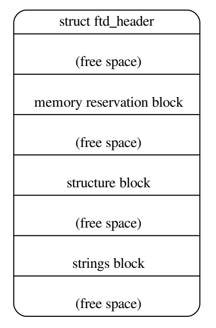
free space 部分可能不存在,但在某些情况下,它们可能需要满足各个块的对齐约束(参见 第 5.6 节 )。
5.1 Versioning
自该格式的原始定义以来,已经定义了几个版本的扁平设备树结构。Header 中的字段给出版本,以便客户程序可以确定设备树是否以兼容格式编码。
本文档仅描述了该格式的第 17 版。DTSpec-compliant 引导程序应提供版本 17 或更高版本的设备树,并应提供与版本 16 向后兼容的版本的设备树。DTSpec-compliant 客户程序应接受与版本 17 向后兼容的任何版本的设备树,并且也可以接受其他的版本。
注:版本是关于设备树的二进制结构的,而不是它的内容。
5.2 Header
设备树的 header 布局由以下 C 结构定义。Header 的所有字段都是 32-bit 整数,以 big-endian 格式存储。
Flattened Devicetree Header Fields
1 | |
magicThis field shall contain the value 0xd00dfeed (big-endian).totalsizeThis field shall contain the total size in bytes of the devicetree data structure. This size shall encompass all sections of the structure: the header, the memory reservation block, structure block and strings block, as well as any free space gaps between the blocks or after the final block.off_dt_structThis field shall contain the offset in bytes of the structure block (see Section 5.4) from the beginning of the header.off_dt_stringsThis field shall contain the offset in bytes of the strings block (see Section 5.5) from the beginning of the header.off_mem_rsvmapThis field shall contain the offset in bytes of the memory reservation block (see Section 5.3) from the beginning of the header.versionThis field shall contain the version of the devicetree data structure. The version is 17 if using the structure as defined in this document. An DTSpec boot program may provide the devicetree of a later version, in which case this field shall contain the version number defined in whichever later document gives the details of that version.last_comp_versionThis field shall contain the lowest version of the devicetree data structure with which the version used is backwards compatible. So, for the structure as defined in this document (version 17), this field shall contain 16 because version 17 is backwards compatible with version 16, but not earlier versions. As per Section 5.1, a DTSpec boot program should provide a devicetree in a format which is backwards compatible with version 16, and thus this field shall always contain 16.boot_cpuid_physThis field shall contain the physical ID of the system’s boot CPU. It shall be identical to the physical ID given in the reg property of that CPU node within the devicetree.size_dt_stringsThis field shall contain the length in bytes of the strings block section of the devicetree blob.size_dt_structThis field shall contain the length in bytes of the structure block section of the devicetree blob.
5.3 Memory Reservation Block
5.3.1 目的
Memory Reservation Block 为客户程序提供物理内存中保留的区域列表;也就是说,它不能用于一般的内存分配。它用于保护重要的数据结构不被客户程序覆盖。例如,在某些具有 IOMMU 的系统上,由 DTSpec 引导程序初始化的 TCE(Translation Control Entry)表需要以这种方式进行保护。同样,在客户程序运行时使用的任何引导程序代码或数据都需要保留(例如,Open Firmware 平台上的 RTAS)。DTSpec 不要求引导程序提供任何此类运行时组件,但它并不禁止实现这样做以作为扩展。
更具体地说,客户程序不应访问保留区域中的内存,除非引导程序提供的其他信息明确表明它可以这样做。客户程序可以以指示的方式访问 reserved memory 的指示部分。引导程序可以向客户程序指示 reserved memory 的特定用途的方法可能出现在本文档、它的可选扩展或特定于平台的文档中。
引导程序提供的保留区域可以但不是必须包含 devicetree blob 本身。客户程序应确保在使用此数据结构之前不会覆盖它,无论它是否在保留区域中。
Any memory that is declared in a memory node and is accessed by the boot program or caused to be accessed by the boot program after client entry must be reserved. Examples of this type of access include (e.g., speculative memory reads through a non-guarded virtual page).
This requirement is necessary because any memory that is not reserved may be accessed by the client program with arbitrary storage attributes.
Any accesses to reserved memory by or caused by the boot program must be done as not Caching Inhibited and Memory Coherence Required (i.e., WIMG = 0bx01x), and additionally for Book III-S implementations as not Write Through Required (i.e., WIMG = 0b001x). Further, if the VLE storage attribute is supported, all accesses to reserved memory must be done as VLE=0.
This requirement is necessary because the client program is permitted to map memory with storage attributes specified as not Write Through Required, not Caching Inhibited, and Memory Coherence Required (i.e., WIMG = 0b001x), and VLE=0 where supported. The client program may use large virtual pages that contain reserved memory. However, the client program may not modify reserved memory, so the boot program may perform accesses to reserved memory as Write Through Required where conflicting values for this storage attribute are architecturally permissible.
5.3.2 格式
Memory Reservation Block 由成对的 64-bit big-endian 整数对组成,每一对由以下 C 结构表示。
1 | |
每对都给出了 reserved memory 区域的物理地址和大小(以字节为单位)。这些给定区域 不能 相互重叠。保留块列表 必须 以地址和大小都等于 0 的条目结束。请注意,地址和大小值始终为 64-bit。在 32-bit CPU 上,该值的高 32-bit 被忽略。
Memory Reservation Block 中的每个 uint64_t 以及整个 memory reservation block 都 必须 位于距 devicetree blob 开始的 8-byte 对齐偏移处(参见 第 5.6 节 )。
5.3.3 Memory Reservation Block 和 UEFI
与 /reserved-memory 节点( 第 3.5.4 节 )一样,通过 [UEFI] 引导时,Memory Reservation Block 中的条目也必须列在通过 GetMemoryMap() 获得的系统内存映射中,以防止 UEFI 应用程序分配。Memory Reservation Block 条目 应该 以 EfiReservedMemoryType 类型列出。
5.4 Structure Block
Structure Block 描述了设备树本身的结构和内容。它由一系列带有数据的标记组成,如下所述。这些被组织成线性树结构,如下所述。
Structure Block 中的每个标记,以及 structure block 本身,都 必须 位于距 devicetree blob 开始的 4-byte 对齐偏移处(参见 第 5.6 节 )。
5.4.1 词法结构
Structure Block 由一系列片段组成,每个片段都以一个标记开头,即一个 big-endian 32-bit 整数。一些标记后面会紧随额外的数据,其格式由标记值确定。所有标记都 必须 在 32-bit 边界上对齐,这可能需要在前一个标记的数据之后插入填充字节(值为 0x0)。
五种标记类型如下:
FDT_BEGIN_NODE (0x00000001)标记标志着节点表示的开始。其后 必须 紧随节点的单元名称以作为额外数据。名称以空字符结尾的字符串存储,并且如果有单元地址的话,则 必须 包括单元地址(参见 第 2.2.1 节 )。节点名称后跟零填充字节(如果需要对齐),然后是下一个标记(可以是除FDT_END之外的任何标记)。FDT_END_NODE (0x00000002)标记标志着节点表示的结束。这个标记没有额外的数据,因此紧随其后的是下一个标记(可以是除FDT_PROP之外的任何标记)。FDT_PROP (0x00000003)标记标志着设备树中一个属性表示的开始。其后 必须 紧随描述属性的额外数据。该数据首先包含属性的长度和名称,表示为以下 C 结构:此结构中的两个字段都是 32-bit big-endian 整数。1
2
3
4struct {
uint32_t len;
uint32_t nameoff;
}FDT_NOP (0x00000004)标记会被解析设备树的任何程序忽略。这个标记没有额外的数据,因此紧随其后的是下一个标记。树中的属性或节点定义可以用FDT_NOP标记覆盖以将其从树中删除,而无需在 devicetree blob 中移动树表示的其他部分。FDT_END (0x00000009)标记标志着 structure block 的结束。Structure Block 必须 只有一个FDT_END标记,并且它应该是 structure block 中的最后一个标记。它没有额外的数据,因此紧随其后的字节与 structure block 开头的偏移量等于 devicetree blob header 中的size_dt_struct字段的值。
5.4.2 树结构
设备树结构表示为一棵线性树:每个节点的表示以 FDT_BEGIN_NODE 标记开始,以 FDT_END_NODE 标记结束。节点的属性和子节点(如果有)在 FDT_END_NODE 之前表示,因此这些子节点的 FDT_BEGIN_NODE 和 FDT_END_NODE 标记嵌套在父节点的标记中。
整个 structure block 由根节点的表示(包含所有其他节点的表示)组成,后跟一个 FDT_END 标记以标注整个 structure block 的结束。
更准确地说,每个节点的表示由以下部分组成:
- (可选)任意数量的
FDT_NOP标记 FDT_BEGIN_NODE标记- 节点名称为空终止字符串
- [零填充字节对齐 4-byte 边界]
- 对于节点的每个属性:
- (可选)任意数量的
FDT_NOP标记 FDT_PROP标记- 第 5.4.1 节 中给出的属性信息
- [零填充字节对齐 4-byte 边界]
- (可选)任意数量的
- 这种格式的所有子节点的表示
- (可选)任意数量的
FDT_NOP标记 FDT_END_NODE标记
请注意,此过程要求特定节点的所有属性定义都位于该节点的任何子节点定义之前。虽然如果属性和子节点混合在一起,结构不会有歧义,但处理扁平树所需的代码被此要求简化了。
5.5 Strings Block
Strings Block 包含树中使用的所有属性名称的字符串。这些以空结尾的字符串在本部分中简单地连接在一起,并从 structure block 中通过偏移量引用到 strings block 中。
Strings Block 没有对齐约束,并且可以出现在距 devicetree blob 开头的任何偏移处。
5.6 对齐
devicetree blob 必须 位于一个 8-byte 对齐的地址。为了保持对 32-bit 机器的向后兼容性,某些软件支持 4-byte 对齐,但这并不 DTSpec-compliant。
对于要在没有未对齐内存访问的情况下使用的 memory reservation block 和 structure block 中的数据,它们 必须 位于适当对齐的内存地址。具体来说,memory reservation block 必须 与 8-byte 边界对齐,structure block 必须 与 4-byte 边界对齐。
此外,可以在不破坏子块对齐的情况下重新定位整个 devicetree blob。
如前几节所述,structure block 和 strings block 必须 具有与 devicetree blob 开头对齐的偏移量。为了确保块的内存对齐,确保将设备树作为一个整体加载到与任何子块的最大对齐对齐的地址,即与 8-byte 边界对齐就足够了。DTSpec-compliant 的引导程序 必须 在将 devicetree blob 传递给客户程序之前将其加载到这样一个对齐的地址。如果 DTSpec 客户程序将 devicetree blob 重新定位到内存中,它 应该 只对另一个 8-byte 对齐的地址执行此操作。
6. DEVICETREE SOURCE (DTS) FORMAT (VERSION 1)
DTS(Devicetree Source)格式是设备树的文本表示,其格式可以由 dtc 处理成内核期望的二进制设备树。以下描述不是 DTS 的正式语法定义,而是描述用于表示设备树的基本构造。
DTS 文件的名称 应该 以“.dts”结尾。
6.1 编译器指令
可以从 DTS 文件中包含其他源文件。包含文件的名称应以“.dtsi”结尾。包含的文件又可以包含其他文件。
1 | |
6.2 标签
源格式允许将标签(Label)附加到设备树中的任何节点或属性值。Phandle 和路径引用可以通过引用标签而不是显式指定 phandle 值或节点的完整路径来自动生成。标签仅用于 devicetree 源格式,不编码进 DTB 二进制文件。
标签的长度 必须 在 1 到 31 个字符之间,仅由 Table 6.1 中的字符组成,并且不得以数字开头。
标签是通过在标签名称后附加一个冒号(‘:’)来创建的。引用是通过在标签名称前加上和号(‘&’)来创建的。
| Character | Description |
|---|---|
| 0-9 | digit |
| a-z | lowercase letter |
| A-Z | uppercase letter |
| _ | underscore |
6.3 节点和属性定义
设备树节点使用节点名称和单元地址定义,大括号标记节点定义的开始和结束。它们前面可能有一个标签。
1 | |
节点可能包含属性定义和/或子节点定义。如果两者都存在,则属性 必须 位于子节点之前。
之前定义的节点 可以 被删除。
1 | |
属性定义是以下形式的名称值对:
1 | |
或者是具有以下形式的空(零长度)值的属性:
1 | |
以前定义的属性 可以 被删除。
1 | |
属性值可以定义为 32-bit 整数 cell 的数组、以空字符结尾的字符串、字节字符串或这些的组合。
- cell 数组由空格分隔的 C 样式整数列表的尖括号表示。例子:
1
interrupts = <17 0xc>; - 值可以表示为括号内的算术、按位或逻辑表达式。
1
2
3
4
5
6
7Arithmetic operators
+ add
- subtract
* multiply
/ divide
% modulo1
2
3
4
5
6
7
8Bitwise operators
& and
| or
^ exclusive or
~ not
<< left shift
>> right shift1
2
3
4
5Logical operators
&& and
|| or
! not1
2
3
4
5
6
7
8Relational operators
< less than
> greater than
<= less than or equal
>= greater than or equal
== equal
!= not equal1
2
3Ternary operators
?: (condition ? value_if_true : value_if_false) - 一个 64-bit 值由两个 32-bit cell 表示。例子:
1
clock-frequency = <0x00000001 0x00000000>; - 以空字符结尾的字符串值使用双引号表示(属性值被认为包括以空字符结尾的字符)。例子:
1
compatible = "simple-bus"; - 一个字节串用方括号 [] 括起来,每个字节由两个十六进制数字表示。每个字节之间的空格是可选的。例子: 或等效地:
1
local-mac-address = [00 00 12 34 56 78];1
local-mac-address = [000012345678]; - 值可能有几个逗号分隔的部分,它们连接在一起。例子:
1
2compatible = "ns16550", "ns8250";
example = <0xf00f0000 19>, "a strange property format"; - 在 cell 数组中,对另一个节点的引用将扩展为该节点的
phandle。引用 可以 是 & 后跟一个节点的标签。例子:或者它们 可以 是 & 后跟一个节点的完整路径,用大括号括起来。例子:1
interrupt-parent = < &mpic >;1
interrupt-parent = < &{/soc/interrupt-controller@40000} >; - 在 cell 数组之外,对另一个节点的引用将扩展到该节点的完整路径。例子:
1
ethernet0 = &EMAC0; - 标签也 可以 出现在属性值的任何部分之前或之后,或者在 cell 数组的 cell 之间,或者在字节串的字节之间。例子:
1
2
3reg = reglabel: <0 sizelabel: 0x1000000>;
prop = [ab cd ef byte4: 00 ff fe];
str = start: "string value" end: ;
6.4 文件布局
版本 1 DTS 文件具有整体布局:
1 | |
/dts-v1/; 必须 存在以将文件标识为版本 1 DTS(没有此标记的 dts 文件将被 dtc 视为处于过时的版本 0 中,除了其他小的但不兼容的更改之外,它使用不同的整数格式)。
Memory reservations(参见 第 5.3 节 )由以下形式的行表示:
1 | |
其中 <address> 和 <length> 是 64-bit C-style 整数,例如,
1 | |
这 / { ... }; 部分定义了设备树的根节点,所有设备树数据都包含在其中。
支持 C-style( /* ... \*/ )和 C++-style( // )注释。
BIBLIOGRAPHY
[IEEE1275] Boot (Initialization Configuration) Firmware: Core Requirements and Practices, 1994, This is the core standard (also known as IEEE 1275) that defines the devicetree concept adopted by the DTSpec and ePAPR. It is available from Global Engineering (http://global.ihs.com/).
[b7] Open Firmware Recommended Practice: Interrupt Mapping, Version 0.9, Open Firmware Working Group, 1996 (http://devicetree.org/open-firmware/practice/imap/imap0_9d.pdf)
[CHRP] PowerPC Microprocessor Common Hardware Reference Platform (CHRP) Binding, Version 1.8, Open Firmware Working Group, 1998 (http://devicetree.org/open-firmware/bindings/chrp/chrp1_8a.ps). This document specifies the properties for Open PIC-compatible interrupt controllers.
[PAPR] Power.org Standard for Power Architecture Platform Requirements, power.org
[b18] The Open Programmable Interrupt Controller (PIC) Register Interface Specification Revision 1.2, AMD and Cyrix, October 1995
[EPAPR] Power.org Standard for Embedded Power Architecture Platform Requirements, power.org, 2011, https://www.power.org/documentation/power-org-standard-for-embedded-power-architecture-platform-requirements-epapr-v1-1-2/
[UEFI] Unified Extensable Firmware Interface Specification v2.8 Errata A, February 2020, UEFI Forum