i.MX RT1060 Manufacturing User's Guide
Document identifier: IMXRT1060MFUUG
Rev. 3, 29 June 2020
1 引言
该文档描述了 i.MX RT 设备的可引导映像的生成。还说明了 i.MX RT BootROM 和 MCUBOOT-based Flashloader 的交互过程,以及将可引导映像编程到外部闪存中的过程,外部闪存可以是:
- QuadSPI NOR / Octal Flash / HyperFlash
- Serial NAND
- eMMC
- SD
- Parallel NOR
- SLC raw NAND
- SPI NOR/EEPROM
i.MX RT BootROM 驻留在 ROM 中并且能够装载 RAM。Flashloader 会被装载到 SRAM 中,以便从引导设备中将引导映像装载到 RAM。它还会验证和执行引导映像。
本文档介绍 Flashloader,它是 i.MX RT BootROM 的一个配套工具,也是一个用于将引导映像编程到可引导设备的完整解决方案。Flashloader 是在 SRAM 中运行的,因此应通过 ROM serial download interface 将其下载到 SRAM。Flashloader 会进行一些准备工作并配置用于引导的设备。它在可引导介质上创建引导配置结构、帮助对加密映像进行编程、生成密钥 blob,并使用用于下载引导映像的 MCUBOOT 命令接口协议与串行外设(如 USB 和 UART)上的 master 进行通信。
它还采用了 elftosb 实用程序。elftosb 实用程序将 elf 映像转换为 i.MX RT 设备的已签名、已加密和可引导的映像。它还会创建所有引导结构,如映像向量表、引导数据。它生成使用 NXP 签名工具(cst)进行代码签名或加密所需的输入命令序列文件。它还调用 cst 来生成签名,并将其包装成 BootROM 可接受的引导映像。
本文档介绍了 MfgTool2.exe(Manufacturing Tool)在制造环境中用于生产设备(使用所有可用工具在可引导介质上编程引导映像)的用法。
2 概述
2.1 i.MX RT BootROM
i.MX RT BootROM 是所有 i.MX RT 设备的标准引导加载程序。它驻留在 ROM 中,并支持从外部闪存设备(XIP 和 non-XIP)中引导。它还通过 UART 或 USB-HID 接口向 i.MX RT 设备的内部 RAM 提供串行下载器功能。
i.MX RT BootROM 是现有 i.MX MPU ROM bootloader 的一个特定实现。i.MX RT BootROM 提供串行下载器功能以使用 SDP 命令接口进行闪存编程。有关其他信息,请参阅 i.MX RT1060 processor reference manual 中的“System Boot”。使用 MfgTool 应用程序可以将 MCU Boot based flashloader 下载到内部 SRAM 中。然后,flashloader 代码执行开始,并通过 MCU Boot 接口启用闪存编程功能。
2.2 MCUBOOT-based Flashloader
MCUBOOT-based Flashloader 是 MCU Bootloader 的一个特定实现。它被用作生产制造的一次性编程辅助工具。Flashloader 支持大多数 MCUBOOT 命令以启用外部闪存编程。有关详细信息,请参阅 MCU Flashloader Reference Manual。
2.3 主机实用程序
MfgTool 是一个 GUI 主机程序,用于在串行下载器模式下与运行 i.MX RT BootROM 的设备进行交互。它还可以用于通过与 Flashloader 交互来对应用程序映像进行编程。
blhost 是一个 CLI 主机程序,用于与运行 MCUBOOT-based bootloaders 的设备进行交互。它是 MfgTool 的一部分。
elftosb 实用程序是一个 CLI 主机程序,用于为 i.MX RT BootROM 生成可引导映像。
cst 是一个 CLI 主机程序,用于为 i.MX RT BootROM 生成证书、映像签名和加密映像。
2.4 术语
Table 1 总结了本文档中包含的术语和缩写。
| Terminology | Description |
|---|---|
| MCUBOOT | MCU Bootloader |
| KeyBlob | KeyBlob is a data structure that wraps the DEK for image decryption using the AES-CCM algorithm |
| DEK | "Key" used to decrypt the encrypted bootable image |
| SB file | The SB file is the NXP binary file format for bootable images. The file consists of sections, sequence of bootloader commands, and data that assists MCU Bootloader in programming the image to target memory. The image data can also be encrypted in the SB file. The file can be downloaded to the target using the MCU Bootloader receive-sb-file command. |
| CST | Code Signing Tool |
| XIP | Execute-In-Place |
3 i.MX RT 可引导映像
3.1 目标闪存设备中的可引导映像布局
支持两种引导映像:
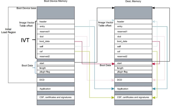
- XIP(Execute-In-Place)引导映像:此类引导映像仅适用于连接到 QuadSPI 或 FlexSPI 接口的 Serial NOR 设备和连接到 WEIM 或 SEMC 接口的 Parallel NOR 设备。引导设备内存与目标内存相同。ROM 可以直接引导这种引导映像。
- Non-XIP 引导映像:此类引导映像通常用于 NAND、SD 和 eMMC 设备。引导设备内存与目标内存不同。ROM 可以从引导设备内存中将引导映像加载到目标内存,然后从目标内存引导。
3.2 引导映像格式
本节介绍引导映像格式和数据结构。elftosb 实用程序可帮助客户自动生成引导映像格式文件。本文档稍后将介绍 elftosb 实用程序的用法。
可引导映像必须具有以下数据结构:
- 映像向量表(IVT,Image Vector Table):一个位于固定地址的指针列表,ROM 会检查该列表以确定可引导映像的其他组件的位置
- 引导数据(Boot Data):一个指示可引导映像位置、映像大小(以字节为单位)和插件标志的表
- 设备配置数据(DCD,Device configuration data)(可选):IC 配置数据配置 DDR/SDRAM 内存
- 用户应用程序和数据(User application and data)
- CSF(可选):通过 CST 生成的用于安全引导的签名块
- KeyBlob(可选):一个数据结构,包含用于加密引导的 wrapped DEK
每个可引导映像都以适当的 IVT 开始。一般来说,对于支持 XIP 特性的外部存储设备,IVT 偏移量为 0x1000,否则为 0x400。例如,对于 RT1060 上的 FlexSPI NOR,IVT 必须从地址 0x60001000 开始(起始地址为 0x6000_0000,IVT 偏移量为 0x1000)。有关更多信息,请参阅相应的处理器参考手册。
3.2.1 IVT 和 Boot Data
IVT 是 BootROM 从引导设备中读取的数据结构。此数据结构提供包含执行成功引导所需的数据组件的可引导映像。
有关详细信息,请参阅设备参考手册的 System Boot 章节中的 Program image 小节。
| Offset | Field | Description |
|---|---|---|
| 0x00 - 0x03 | header |
|
| 0x04 - 0x07 | entry | Absolute address of the first instruction to execute from the image, or the vector address of the image |
| 0x08 - 0x0b | reserved1 | Reserved for future use, set to 0 |
| 0x0c - 0x0f | dcd | Absolute address of the image DCD. It is optional, so this field can be set to NULL if no DCD is required |
| 0x10 - 0x13 | boot_data | Absolute address of the boot data |
| 0x14 - 0x17 | self | Absolute address of the IVT |
| 0x18 - 0x1b | csf | Absolute address of the Command Sequence File (CSF) used by the HAB library |
| 0x1c - 0x1f | reserved2 | Reserved, set to 0 |
3.2.2 Boot Data 结构
| Offset | Field | Description |
|---|---|---|
| 0x00-0x03 | start | Absolute address of the bootable image |
| 0x04-0x07 | length | Size of the bootable image |
| 0x08-0x0b | plugin | Plugin flag, set to 0 because plugin boot is not supported on the RT1010 |
3.3 签名映像
可引导映像可以通过 CST 工具进行签名。该工具根据给定的输入命令序列文件(csf 文件)生成由命令序列和签名组成的二进制文件格式的 CSF 数据。有关更多详细信息,请参阅 CST 发行包中的文档。
在本文档中,将介绍一种使用 elftosb 实用程序生成签名映像的简单方法。
3.4 加密映像
有两种类型的加密映像格式:
已加密的 XIP 映像格式
Flashloader 在对设备上的映像进行编程时使用 AES CTR 算法生成加密的 XIP 图像。在执行时,硬件引擎进行动态解密。
通过 CST 生成的加密映像
为了提高安全级别,可以通过 CST 对可引导映像进行签名和进一步加密。KeyBlob 必须在设备上生成。如果发生任何安全违规,硬件将删除所有敏感密钥,从而无法克隆敏感密钥。
在本文档中,将介绍一种使用 elftosb 实用程序生成签名映像的简单方法。
4 生成 i.MX RT 可引导映像
i.MX RT 设备有两种类型的可引导映像。
- 普通引导映像:这种类型的映像可以直接通过 BootROM 引导。
- 插件式引导映像:这种类型的映像可用于从 BootROM 本身不支持的设备中加载引导映像。
两种类型的映像都可以针对不同的生产阶段和不同的安全级别要求进行签名和加密:
- 未签名映像:映像不包含与验证相关的数据,在开发阶段使用。
- 已签名映像:映像包含与验证相关的数据(CSF 部分),在生产阶段使用。
- 已加密映像:映像包含加密的应用数据和验证相关数据,在安全要求较高的生产阶段使用。
可以使用 elftosb 实用程序生成上述类型的可引导映像。elftosb 实用程序的详细用法可在 elftosb Users Guide 中找到。
4.1 elftosb 实用程序简介
elftosb 实用程序是一个 CLI 主机程序,用于为 i.MX RT BootROM 生成 i.MX RT 可引导映像。该实用程序还生成带有命令序列和可引导映像的包装的二进制文件。要创建 SB 文件,请使用命令行选项和输入文本文件(也称为 BD 或命令文件)。
4.1.1 elftosb 实用程序选项
Table 4 显示了用于创建 i.MX RT 可引导映像的命令行选项。
| Option | Description |
|---|---|
| -f | Specify the bootable image format To create the i.MX RT bootable image, the usage for family argument "-f" is: "-f imx" To create the SB file, the usage is: "-f kinetis" |
| -c | Command file to generate corresponding bootable image For example, "-c program_flexspi_nor_hyperflash.bd" |
| -o | Output file path For example, "-o ivt_flashloader.bin" |
| -V | Print extra detailed log information |
| -? | Print help info |
4.1.2 BD 文件
每个 BD 文件由以下四个块组成:options、sources、constants、section
- 映像路径在“sources”块中定义。
- 常量变量在“constants”块中定义。
- 内存配置和编程相关操作在“section”块中定义。
elftosb 实用程序支持两种类型的 BD 文件。第一种文件用于 i.MX RT 可引导映像生成。在使用 elftosb 实用程序生成引导映像期间,“-f imx”选项是必需的。第二种文件包含用于内存编程的命令。在此用例中,“-f kinetis”标志是强制要求的。
4.1.3 用于 i.MX RT 可引导映像生成的 BD 文件
用于 i.MX RT 可引导映像生成的 BD 文件通常由四个块组成。这些块是 options、sources、constants 和 section。
4.1.3.1 Options 块
Table 5 显示了用于生成可引导映像的 Options 块的选项。
| Options | Description |
|---|---|
| Flags | Generates unsigned, signed, encrypted boot images, and plugin images:
|
| startAddress | Provides the starting address of the target memory where image should be loaded by ROM. |
| ivtOffset | Provides offset where the IVT data structure must appear in the boot image. The default is 0x400 if not specified. The valid value is 0x400 or 0x1000 for i.MX RT boot image. |
| initialLoadSize | Defines the start of the executable image data from elf or the srec file. The default value is 0x2000 if not specified. In general, this value should be 0x1000 or 0x2000. |
| DCDFilePath | Defines the path to DCD file. If not specified, the DCD pointer in the IVT will be set to NULL (0) else the dcd file contents will be loaded at offset 0x40 from ivtOffset. The dcd file size is limited to (initialLoadSize - ivtOffset-0x40). |
| cstFolderPath | Defines the path for platform dependent CST. (windows, linux) If not specified, elftosb tool will search for cst executable in same path as elftosb executable. |
| entryPointAddress | Provides the entry point address for ELF or SREC image. If not specified, ELF image uses its source image entry point address but SREC image will use default entry point address (0). |
4.1.3.2 Sources 块
通常,该部分提供所有应用程序映像路径。目前,i.MX RT 可引导映像生成支持 ELF 文件和 SREC 文件,例如:
1 | |
4.1.3.3 Constants 块
Constants 块提供一个常量变量,用于生成 CSF 数据以进行映像验证和解密。对于未签名映像,Constants 块是可选的。下面列出了支持的常量。
1 | |
4.1.3.4 Section 块
Section 块用于创建 i.MX RT 可引导映像的 section,例如,CSF 数据的所有 section。对于未签名映像,Section 块是固定的空白 section,如下所示。
1 | |
对于已签名和已加密的映像,elftosb 实用程序定义了以下 sections,以生成 CST 生成 CSF 数据所需的 CSF 描述符文件。
- SEC_CSF_HEADER
该 section 定义了生成 CSF 头所需的必要元素以及用于其余 CSF 中其他 section 的默认值。
| Element | Description |
|---|---|
| Header_Version | HAB library version Valid values: 4.0, 4.1, 4.2, 4.3 |
| Header_HashAlgorithm | Default Hash Algorithm Valid values: sha1, sha256, sha512 |
| Header_Engine | Default Engine Valid values: ANY, DCP, CAAM, SW |
| Header_EngineConfiguration | Default Engine Configuration Recommended value: 0 |
| Header_CertificateFormat | Default Certificate Format Valid values: WTLS, X509 |
| Header_SignatureFormat | Default signature format Valid values: PKCS, CMS |
| Header_SecurityConfiguration | Fused security configuration Valid values: Engineering, Production |
| Header_UID | Generic (matches any value) U0, U1,... Un where each Ui=0..255 and n<255 |
| Header_CustomerCode | Value expected in "customer code" fuses 0..255 |
示例 section 块如下所示。
1 | |
- SEC_CSF_INSTALL_SRK
该 section 包含用于验证和安装根公钥的元素,以供后续 section 使用,如下表所示。
| Element | Description |
|---|---|
| InstallSRK_Table | Path pointing to the Super Root Key Table file |
| InstallSRK_Source | SRK index with the SRK table |
| InstallSRK_HashAlgorithm | SRK table hash algorithm. Valid values: SHA1, SHA256 and SHA512 |
示例 section 块如下所示。
1 | |
- SEC_CSF_INSTALL_CSFK
该 section 包含用于验证和安装公钥的元素,以供后续 section 使用。
| Element | Description |
|---|---|
| InstallCSFK_File | File path pointing to CSFK certificate |
| InstallCSFK_CertificateFormat | CSFK certificate format Valid values: WTLS, X509 |
1 | |
- SEC_CSF_INSTALL_NOCAK
Install NOCAK 命令验证并安装用于快速验证机制(HAB 4.1.2 及更高版本)的公钥。使用这种机制,一个密钥用于所有签名。下表列出了 install NOCAK 命令参数。
| Element | Description |
|---|---|
| InstallNOCAK_File | File path pointing to CSFK certificate |
| InstallNOCAK_CertificateFormat | CSFK certificate format Valid values: WTLS, X509 |
示例 section 块如下所示。
1 | |
- SEC_CSF_AUTHENTICATE_CSF
该 section 用于使用上一节中提到的 CSFK 对执行它的 CSF 进行验证。有关详细信息,请参阅下表。
| Element | Description |
|---|---|
| AuthenticateCSF_Engine | CSF signature hash engine Valid values: ANY, SAHARA, RTIC, DCP, CAAM and SW |
| AuthenticateCSF_EngineConfiguration | Configuration flags for the hash engine. Note that the hash is computed over an internal RAM copy of the CSF Valid engine configuration values corresponding to engine name. |
| AuthenticateCSF_SignatureFormat | CSF signature format Valid values: PKCS1, CMS |
示例 section 块如下所示。
1 | |
- SEC_CSF_INSTALL_KEY
该 section 包含用于验证和安装公钥的元素,以供后续 section 使用,如下表所示。
| Element | Description |
|---|---|
| InstallKey_File | File path pointing to a Public key file |
| InstallKey_VerificationIndex | Verification key index in Key store Valid values: 0, 2, 3, 4 |
| InstallKey_TargetIndex | Target key index in key store Valid values: 2, 3, 4 |
| InstallKey_CertificateFormat | Valid values: WTLS, X509 |
| InstallKey_HashAlgorithm | Hash algorithm for certificate binding. If present, a hash of the certificate specified in the File argument is included in the command to prevent installation from other sharing the same verification key Valid values: SHA1, SHA256, SHA512 |
1 | |
- SEC_CSF_AUTHENTICATE_DATA
该 section 包含用于验证内存中预加载数据真实性的元素。
| Element | Description |
|---|---|
| AuthenticateData_VerificationIndex | Verification key index in key store |
| AuthenticateData_Engine | Data signature hash engine Valid values: ANY, DCP, CAAM, SW |
| AuthenticateData_EngineConfiguration | Configuration flags for the engine |
| AuthenticateData_SignatureFormat | Data signature format Valid values: PKCS1, CMS |
| AuthenticateData_Binding | 64-bit unique ID (UID) for binding. If present, authentication succeeds only if the UID fuse value matches this argument, and the TYPE fuse value matches the Security Configuration argument from the Header command Valid values: U0, U1, ... U7 with Ui: 0, ..., 255. UID bytes separated by commas |
示例 section 块如下所示:
1 | |
- SEC_CSF_INSTALL_SECRET_KEY
该 section 包含用于将密钥安装到用于 KeyBlob 解密的 MCU 密钥存储的元素。该 section 是加密映像生成所必需的,而不是签名映像所必需的。
| Element | Description |
|---|---|
| SecretKey_Name | Specifies the file path used for CST to generate the random decryption key file |
| SecretKey_Length | Key length in bits Valid values: 128, 192, and 256 |
| SecretKey_VerifyIndex | Master KEK index Valid values: 0 or 1 |
| SecretKey_TargetIndex | Target secret key store index Valid values: 0-3 |
| SecretKey_BlobAddress | Internal or external DDR address |
示例 section 块如下所示:
1 | |
- SEC_CSF_DECRYPT_DATA
该 section 是加密映像生成所必需的,而不是签名映像所必需的。它包含用于使用存储在密钥存储中的密钥解密和验证代码/数据块列表的必要元素,如下表所示。
| Element | Description |
|---|---|
| Decrypt_Engine | MAC engine Valid value: CAAM, DCP |
| Decrypt_EngineConfiguration | Configuration flags for the engine Default value: 0 |
| Decrypt_VerifyIndex | Secret key index in the Secret key store Valid values: 0-3 |
| Decrypt_MacBytes | Size of MAC in bytes If engine is CAAM, the valid value is even number between 4-16. The recommended value is 16. If engine is DCP, the valid value is 16. |
示例 section 块如下所示。
1 | |
- SEC_NOP
该 section 中的命令无效。它也没有参数。
示例 section 块如下所示。
1 | |
- SEC_SET_MID
Set MID 命令选择一系列 fuse 位置以用作制造标识符(MID,manufacturing identifier)。在使用 Install Key 命令中带有 MID 绑定标志的密钥进行验证时,MID 值与 Authenticate Data 签名绑定。
| Element | Description |
|---|---|
| SetMID_Bank | Fuse bank containing MID. Valid values: 0, …, 255 |
| SetMID_Row | Starting row number of MID within bank. Valid values: 0, …, 255 |
| SetMID_Fuse | Starting fuse of MID within row. Valid values: 0, …, 255 |
| SetMID_Bits | Number of bits for MID. Valid values: 0, …, 255 |
示例 section 块如下所示:
1 | |
- SEC_SET_ENGINE
Set Engine 命令为给定算法选择默认引擎和引擎配置。
| Element | Description |
|---|---|
| SetEngine_Engine | Engine Use ANY to restore the HAB internal criteria. Valid values: ANY, SAHARA, RTIC, DCP, CAAM and SW |
| SetEngine_HashAlgorithm | Hash algorithm Valid values: SHA1, SHA256 and SHA512 |
| SetEngine_EngineConfiguration | Configuration flags for the engine. Valid engine configuration values corresponding to engine name. |
示例 section 块如下所示:
1 | |
- SEC_INIT
Init 命令在退出内部 BootROM 时初始化指定的引擎特性。
| Element | Description |
|---|---|
| INIT_Engine | Engine to initialize Valid value – SRTC |
| INIT_Features | Comma-separated list of features to initialize Valid engine feature corresponding to engine argument. |
示例 section 块如下所示:
1 | |
- SEC_UNLOCK
Unlock 命令可防止在退出内部 BootROM 时锁定指定的引擎特性。
| Element | Description |
|---|---|
| Unlock_Engine | Engine to unlock Valid values: SRTC, CAAM, SNVS and OCOTP |
| Unlock_features | Comma-separated list of features to unlock Valid engine feature corresponding to engine argument. |
| Unlock_UID | Device specific 64-bit UID U0, U1, …, U7 with Ui=0...255 UID bytes separated by commas |
示例 section 块如下所示:
1 | |
4.1.4 用于内存编程的 BD 文件
通常,“load”、“enable”和“erase”命令是 BD 文件中用于内存编程的最常用命令。
- “load”命令:该命令加载原始二进制文件、srec 文件、elf 文件和十六进制字符串。它还支持将数据加载到外部存储设备,例如:
- Load itcm_boot_image.bin > 0x8000;(将数据加载到 ITCM)
- Load flexspi_nor_boot_image.bin > 0x60001000;(将数据加载到内存映射的存储设备)
- Load semc_nor_boot_image.bin > 0x80001000;(将数据加载到 SEMC NOR,内存映射的存储设备)
- Load spinand boot_image.bin > 0x04;(将数据加载到 SPI NAND)
- Load sdcard boot_image.bin > 0x400;(将数据加载到 SD Card)
- Load mmccard boot_image.bin > 0x400;(将数据加载到 eMMC)
- Load spieeprom boot_image.bin > 0x400;(将数据加载到 SPI EEPROM/NOR)
- Load semcnand boot_image.bin > 0x400;(通过 SEMC 将数据加载到 SLC raw NAND)
- Load fuse 0x00000000 > 0x10;(将数据加载到 Fuse block)
- “enable”命令:该命令配置外部存储设备,例如:
- Enable flexspinor 0x1000
- Enable spinand 0x1000
- Enable sdcard 0x1000
- Enable mmccard 0x1000
- Enable spieeprom 0x1000
- Enable semcnor 0x1000
- Enable semcnand 0x1000
- “erase”命令:该命令擦除所选存储设备中的存储范围。例如:
- Erase 0x60000000..0x60010000(从 FlexSPI NOR 中擦除 64 KB)
- Erase spinand 0x4..0x08(从 SPI NAND 中擦除 4 blocks)
- Erase sdcard 0x400..0x14000
- Erase mmccard 0x400..0x14000
- Erase spieeprom 0x400..0x14000
- Erase semcnand 0x400..0x14000
4.2 生成未签名的普通 i.MX RT 可引导映像
通常,在开发阶段会生成并编程未签名的可引导映像到目标存储器。
elftosb 实用程序支持使用工具链生成的选项、BD 文件和 ELF/SREC 文件生成未签名的可引导映像。
以 Flashloader 项目为例,以下是为 Flashloader 创建可引导映像的步骤。
步骤 1:创建一个 BD 文件。对于未签名映像的创建,“constants”块是可选的,如下所示。
1 | |
创建 BD 文件后,将其放入 elftosb 实用程序可执行文件的同一文件夹中。
步骤 2:将发行包中提供的 Flashloader.srec 复制到 elftosb 实用程序可执行文件的同一文件夹中。
步骤 3:使用 elftosb 实用程序生成可引导映像。

然后,elftosb 实用程序会生成两个可引导映像。
第一个是 ivt_flashloader_unsigned.bin。从 0 到 ivt_offset 的内存区域被填充字节(0x00s)填充。
第二个是 ivt_flashloader_nopadding.bin,其直接从 ivtdata 开始,并且在 ivt 之前不进行任何填充。
4.3 生成已签名的普通 i.MX RT 可引导映像
要使用 elftosb 实用程序生成一个已签名可引导的映像,需要执行以下步骤:
步骤 1:创建一个 BD 文件。其内容可以如下。
1 | |
创建 BD 文件后,将其放入 elftosb 实用程序可执行文件的同一文件夹中。
步骤 2:将发行包中提供的 Flashloader.srec 复制到 elftosb 实用程序可执行文件的同一文件夹中。
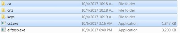
步骤 3:将“cst”可执行文件、“crts”文件夹和“keys”文件夹从“<cst_installation_dir>”复制到 elftosb 实用程序可执行文件的同一文件夹中。
步骤 4:使用 elftosb 实用程序生成可引导映像。

然后,elftosb 实用程序会生成两个可引导映像。第一个是 ivt_flashloader_signed.bin。从 0 到 ivt_offset 的内存区域被填充字节(0x00s)填充。第二个是 ivt_flashloader_signed_nopadding.bin,其直接从 ivt_offset 开始。CSF section 已成功生成并附加到未签名的可引导映像。
4.4 生成已加密的普通 i.MX RT 可引导映像
要生成加密映像,请执行以下步骤:
步骤 1:创建一个 BD 文件。
1 | |
步骤 2:将发行包中提供的 Flashloader.srec 复制到 elftosb 实用程序可执行文件的同一文件夹中。
步骤 3:将“cst”可执行文件、“crts”文件夹和“keys”文件夹从“<cst_installation_dir>”复制到 elftosb 实用程序可执行文件的同一文件夹中。
步骤 4:使用 elftosb 实用程序生成加密的可引导映像。
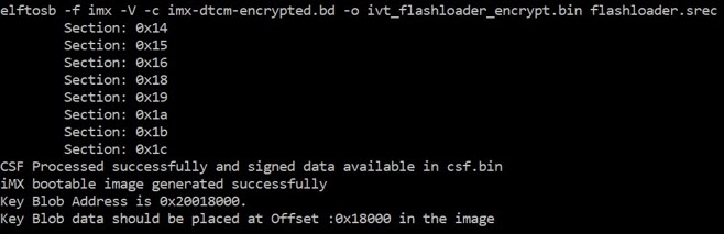
然后,elftosb 实用程序会生成两个可引导映像。第一个是 ivt_flashloader_encrypt.bin。从 0 到 ivt_offset 的内存区域被填充字节(0x00s)填充。
上述示例中的 Key Blob offset 将在后面的 section 中使用。
第二个是 ivt_flashloader_encrypt_nopadding.bin,其直接从 ivt_offset 开始。CSF section 已成功生成并附加到未签名的可引导映像。
步骤 5:使用 Flashloader 生成 KeyBlob section。
elftosb 实用程序生成的加密映像是不完整的,因为 KeyBlob section 必须仅在 SoC 端生成。
有两种方法可以生成 KeyBlob 块:
- 使用 Flashloader 和 blhost 支持的
generate-key-blob <dek_file> <blob_file>命令生成 KeyBlob。有关详细信息,请参阅附录。 - 在制造过程中生成 KeyBlob 并使用 KeyBlob option 块。有关更多信息,请参见下一章。
4.5 生成插件式引导映像
生成插件式引导映像的生成过程与普通引导映像的过程类似。唯一的区别是“options”块中“flags”元素中的第 4 位必须设置为 1。换句话说,插件式引导映像的有效标志值列表是 {0x10, 0x18, 0x1c}。
插件式引导映像生成的示例 BD 文件如下所示。
1 | |
5 生成用于可引导映像编程的 SB 文件
为了简化制造过程,flashloader 和可引导映像支持的所有命令都可以包装到单个 SB 文件中。即使应用程序有任何变化,MfgTool 仍然使用这个 SB 文件来制造。SB 文件可以单独更新,而无需更新 MfgTool 使用的脚本。
在本章中,将使用前一章的方法创建一个可引导映像。然后使用可引导映像生成相应的 SB 文件。首先要准备 BD 文件以为可引导映像生成 SB 文件。
5.1 生成用于 FlexSPI NOR 映像编程的 SB 文件
5.1.1 生成普通可引导映像
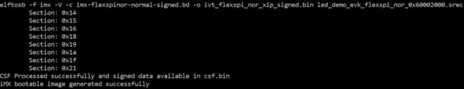
例如,在 RT1060 中,FlexSPI NOR 存储器从地址 0x6000_0000 开始,IVT 从偏移量 0x1000 开始。按照 4.2 生成未签名的普通 i.MX RT 可引导映像 和 BD 文件生成中的步骤,这里是使用 elftosb 实用程序为 FlexSPI NOR 创建可引导映像的方法。发行包中提供了所有 BD 文件。下图参考了生成签名映像的示例命令。
运行上述命令后,后缀为“_nopadding.bin”的文件可通过基于此二进制文件的后续 SB 文件进入目标内存。
5.1.2 生成用于明文 FlexSPI NOR 映像编程的 SB 文件
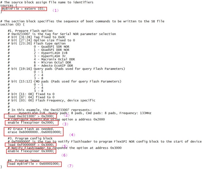
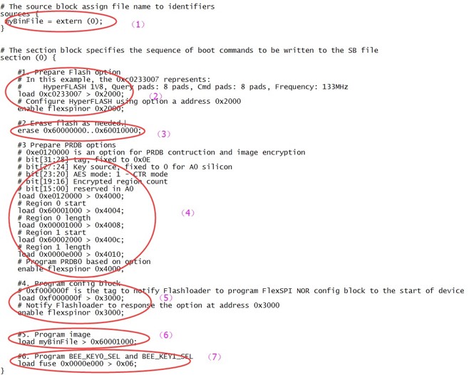
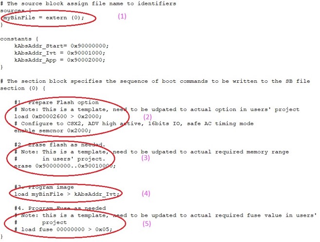
通常,用于 FlexSPI NOR 引导的 BD 文件由 7 个部分组成。
- 在 sources 块中提供可引导映像文件路径。
- 在 section 块中提供 FlexSPI NOR Configuration Option 块。
- 要启用 FlexSPI NOR 访问,必须在 option 块之后使用“enable”命令。
- 如果闪存设备没有被擦除,在将数据编程到闪存设备之前需要一个“erase”命令。擦除操作是耗时的,并且在制造过程中对于空白闪存设备(出厂设置)是不需要的。
- FlexSPI NOR 引导需要 FlexSPI NOR Configuration Block(FNORCB)。要对 FlexSPI NOR Configuration Option 块生成的 FNORCB 进行编程,必须首先将一个特殊的幻数“0xF000000F”加载到 RAM 中。
- 要通知闪存 flashloader 对 FNORCB 进行编程,必须在加载幻数后使用“enable”命令。
- 完成上述操作后,flashloader 可以通过 FlexSPI 模块使用 load 命令将可引导映像二进制文件编程到 Serial NOR Flash 中。
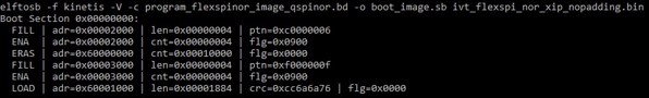
包含上述步骤的示例如下图所示。
下面是使用 elftosb 实用程序、ivt_flexspi_nor_xip.bin 和 BD 文件生成 SB 文件的示例,如下图所示。
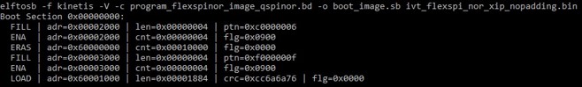
在上述命令之后,将在包含 elftosb 实用程序可执行文件的同一文件夹中创建一个名为 boot_image.sb 的文件。
5.1.3 生成用于 FlexSPI NOR 映像加密和编程的 SB 文件
通常,用于 FlexSPI NOR 映像加密和编程的 BD 文件包含 7 个步骤。
- 在 sources 块中提供可引导映像文件路径。
- 使用 FlexSPI NOR Configuration Option 块启用 FlexSPI NOR 访问。
- 如果闪存设备不是空白的,请擦除它。擦除操作是耗时的,并且在制造过程中对于空白闪存设备(出厂设置)是不需要的。
- 使用 PRDB option 块启用映像加密。
- 使用幻数对 FNORCB 进行编程。
- 通过 FlexSPI 模块将引导映像二进制文件编程到 Serial NOR。
- 启用加密 XIP fuse 位。
生成 SB 文件的步骤与上一节相同。
5.2 生成用于 FlexSPI NAND 映像编程的 SB 文件
对于 FlexSPI NAND 引导,IVT 偏移始终为 0x400。但是,为了减少计算每个固件区域的起始地址的工作量,Flashloader 支持将 FlexSPI NAND 引导映像以块粒度编程到相应的固件区域。因此,将使用没有“_nopadding”后缀的可引导映像。
5.2.1 生成用于 FlexSPI NAND 映像编程的 SB 文件
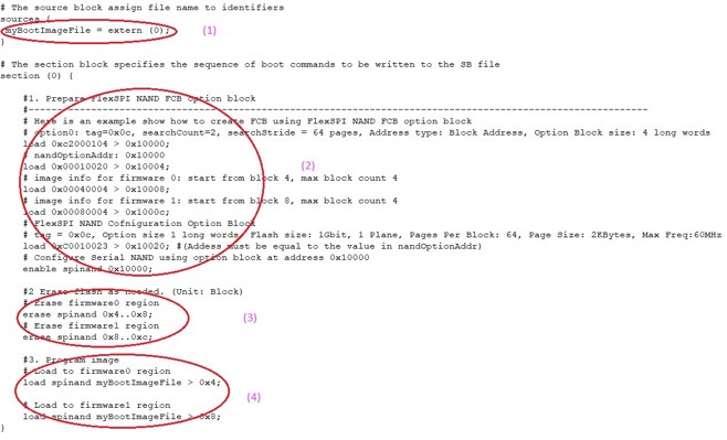
通常,用于 FlexSPI NAND 映像编程的 SB 文件包含 4 个步骤。
- 在 sources 块中提供可引导映像文件路径。
- 使用 FlexSPI NAND Configuration Option 块启用 FlexSPI NAND 访问。
- 根据需要擦除 SPI NAND。
- 通过 FlexSPI 模块将引导映像二进制文件编程到 Serial NAND。
5.2.2 生成用于已加密 FlexSPI NAND 映像和 KeyBlob 编程的 SB 文件
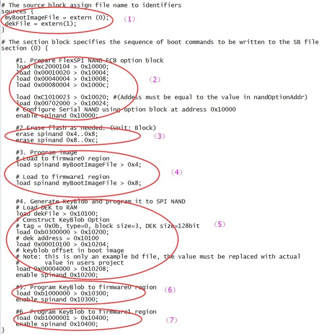
通常,用于使用 KeyBlob 进行 FlexSPI NAND 映像编程的 BD 文件包含 7 个步骤。
- 在 sources 块中提供可引导映像文件路径。
- 使用 FlexSPI NAND Configuration Option 块启用 FlexSPI NAND 访问。
- 根据需要擦除 SPI NAND 设备。
- 通过 FlexSPI 模块将引导映像二进制文件编程到 Serial NAND。
- 使用 KeyBlob Option 块更新 KeyBlob 信息。
- 将 KeyBlob 块编程到固件 0 的 SPI NAND。
- 将 KeyBlob 块编程到固件 1 的 SPI NAND。
示例 BD 文件如下图所示。
5.3 生成用于 SD 映像编程的 SB 文件
SD 映像始终从偏移量 0x400 开始。由 elftosb 实用程序生成的带有“_nopadding.bin”的 i.MX RT 引导映像将用于编程。
5.3.1 生成用于 SD 映像编程的 SB 文件的步骤
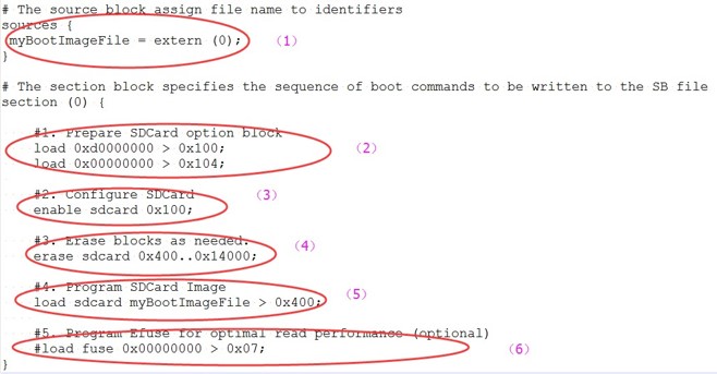
一般来说,在 BD 文件中有 6 个步骤以将可引导映像编程到 SD card 上。
- 在 sources 块中提供可引导映像文件路径。
- 准备 SDCard option 块。
- 使用 enable 命令启用 SDCard 访问。
- 根据需要擦除 SDCard 内存。
- 将引导映像二进制编程到 SDCard。
- 将优化的 SD 引导参数编程到 Fuse(可选,实际项目中不需要时去掉)。
下图展示了一个示例。
加密 SD 引导映像和 KeyBlob 编程生成 SB 文件的步骤类似于 FlexSPI NAND。有关更多详细信息,请参见下面的示例。
1 | |
5.4 生成用于 eMMC 映像编程的 SB 文件
eMMC 映像始终从偏移量 0x400 开始。由 elftosb 实用程序生成的带有“_nopadding.bin”的 i.MX RT 引导映像将用于编程。
eMMC 引导模式有两种:普通引导和快速引导。
5.4.1 普通模式
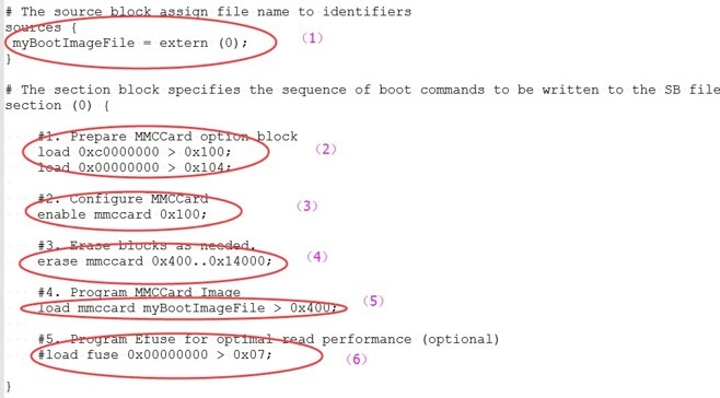
BD 文件中有 6 个步骤将可引导映像编程到 eMMC 以实现普通引导模式。
- 在 sources 块中提供可引导映像文件路径。
- 准备 eMMC option 块。
- 使用 enable 命令启用 eMMC 访问。
- 根据需要擦除 eMMC 内存。
- 将引导映像二进制编程到 eMMC。
- 将优化的 eMMC 引导参数编程到 Fuse(可选,实际项目中不需要的话去掉)。
5.4.2 快速模式
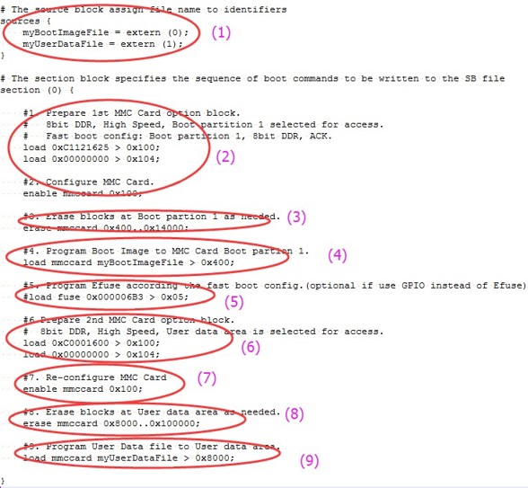
BD 文件中有 9 个步骤将可引导映像编程到 eMMC 以实现快速引导模式。
- 在 sources 块中提供可引导映像文件路径。
- 准备 eMMC option 块并使用 enable 命令启用 eMMC 访问。
- 根据需要擦除 eMMC 内存。
- 将引导映像二进制编程到 eMMC。
- 将优化的 eMMC 引导参数编程到 Fuse(可选,实际项目中不需要的话去掉)。
- 准备第二个 eMMC option 块。
- 使用新的 option 块重新启用 eMMC 访问。
- 根据需要擦除用户数据区中的数据。
- 加载用户数据文件到用户数据区。
加密 eMMC 引导映像和 KeyBlob 编程的 BD 文件与 SD 类似。
5.5 生成用于 Serial NOR/EEPROM 映像编程的 SB 文件
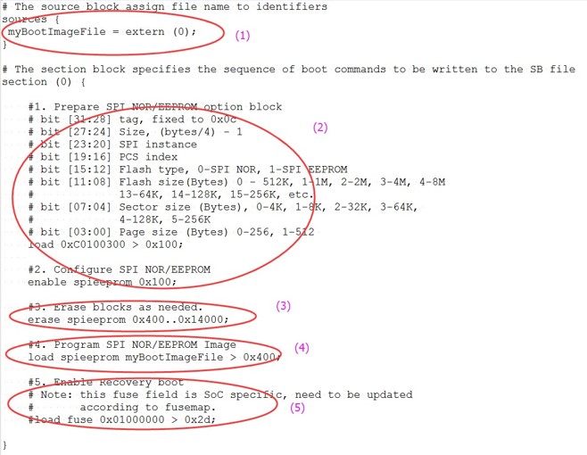
BD 文件中有 5 个步骤将可引导映像编程到 SD card Serial NOR/EEPROM。
- 在 sources 块中提供可引导映像文件路径。
- 准备 Serial NOR/EEPROM option 块并使用 enable 命令启用 Serial NOR/EEPROM 访问。
- 根据需要擦除 Serial NOR/EEPROM 内存。
- 将引导映像二进制编程到 Serial NOR/EEPROM 设备。
- 根据需要通过 Serial NOR/EEPROM 启用恢复引导。
下图展示了一个示例。
加密 SPI EEPRM/NOR Serial NOR/EEPROM 引导映像和 KeyBlob 编程的 BD 文件与 SD 类似。
5.6 生成用于 SEMC NOR 映像编程的 SB 文件
一般来说,在 BD 文件中有 5 个步骤将可引导映像编程到 SD card SEMC NOR。
- 在 sources 块中提供可引导映像文件路径。
- 准备 SEMC NOR option 块并使用 enable 命令启用 SEMC NOR 访问。
- 根据需要擦除 SEMC NOR 内存。
- 将引导映像二进制编程到 SEMC NOR 设备。
- 根据需要将优化的 SEMC NOR 访问参数编程到 Fuse。
下图展示了一个示例 BD 文件。
5.7 生成用于 SEMC NAND 映像编程的 SB 文件
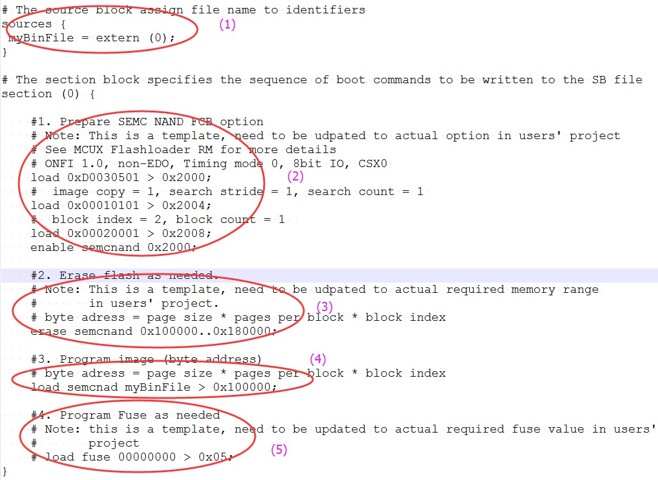
在 BD 文件中有 5 个步骤将可引导映像编程到 SD card SEMC NAND。
- 在 sources 块中提供可引导映像文件路径。
- 准备 SEMC NAND FCB option 块并使用 enable 命令启用 SEMC NAND 访问。
- 根据需要擦除 SEMC NAND 内存。
- 将引导映像二进制编程到 SEMC NAND 设备。
- 根据需要将优化的 SEMC NAND 访问参数编程到 Fuse。
下图展示了一个示例。
5.8 生成用于 fuse 编程的 SB 文件
在某些情况下,必须首先对 fuse 进行编程,以启用所选引导设备或安全级别的特定特性。例如,要启用 eMMC 的快速引导模式,启用 HAB 关闭模式,必须先对 fuse 进行编程。
elftosb 实用程序可以支持使用内置命令 load fuse 对 fuse 进行编程。编程 SRK table 并启用 HAB 关闭模式的示例如下所示。
1 | |
6 编程引导映像
仅 MfgTool 支持可引导映像编程。
6.1 MfgTool
MfgTool 支持 i.MX RT BootROM 和 MCUBOOT-based Flashloader。它可以用于工厂生产环境。MfgTool 可以检测连接到 PC 的 i.MX RT BootROM 设备,并调用“blhost”对连接到 i.MX RT 设备的目标存储设备上的映像进行编程。
MfgTool 配置文件模板随本文档一起提供。它适用于大多数用例,无需任何修改。
6.1.1 MfgTool 目录结构
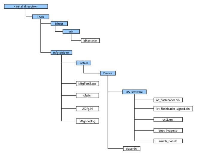
- 在发行包中,mfgtools-rel 文件夹和 blhost 文件夹一起出现在 tools 文件夹中。
- blhost.exe 出现在 blhost/win 文件夹中,MfgTools 可执行文件“MfgTool2.exe”出现在 mfgtools-rel 文件夹中。
- Profiles 文件夹包含其支持设备的配置文件,其中包括“OS Firmware”文件夹和 player.ini 文件。
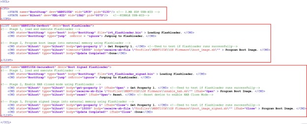
- OS Firmware 文件夹中的 ucl2.xml 文件是 MfgTool 处理的主要 .xml 文件。它包含设备的制造流程。该流程包括设备的标识参数和用于标识连接到 PC 主机的设备的 blhost 命令参数以及更新映像所需的一组 blhost 命令。可以自定义 ucl2.xml 文件以适应自定义设置或制造流程。该文件夹包含供用户参考的示例 XML 文件。下面展示了一个示例的 ucl2.xml。一般来说,它定义了支持的状态和列表。
- “OS firmware”下的“ivt_flashloader.bin”文件是为支持映像编程而发布的 Flashloader。
- “OS firmware”下的“ivt_flashloader_signed.bin”文件是用户在生产阶段为安全引导解决方案生成的可引导 Flashloader 映像文件,可按照 4.3 小节所述生成。
- “OS firmware”下的“boot_image.sb”文件是用户使用 elftosb 实用程序生成的包含命令序列和可引导映像的包装文件。
- “OS firmware”下的“enable_hab.sb”文件是包含命令序列的包装文件,该文件对 Fuse 进行编程以启用 HAB 关闭模式,其由用户使用 elftosb 实用程序生成。
- “Device”配置文件文件夹中的 play.ini 包含制造工具应用程序的可配置参数。
- cfg.ini 和 UICfg.ini 文件为工具 GUI 的外观提供可自定义的参数。工具 GUI 中的 cfg.ini 用于选择列表中的“chip”、“platform”和“name”。参考下面的例子
注:从 Device/OS Firmware 文件夹中的 ucl2.xml 中的列表中选择适当的“chip”,“name”。
1
2
3
4
5
6
7
8[profiles]
chip = MXRT106X
[platform]
board =
[LIST]
name = MXRT106X-DevBoot - UlCfg.ini 用于选择 MfgTool UI 支持的实例数。有效的实例范围是 1-4。
- MfgTool.log 文本文件是调试 MfgTool UI 上报告的故障的有用工具。MfgTool 记录用于调用 blhost 的整个命令行字符串,并将 blhost 在 stdout 上输出的输出响应文本收集到 MfgTool 日志文件中。故障排除时应首先考虑日志文件。
6.1.2 使用 MfgTool 进行映像编程前的准备
有关详细信息,请参阅 4 生成 i.MX RT 可引导映像 和 5 生成用于可引导映像编程的 SB 文件。
6.2 连接到 i.MX RT 平台
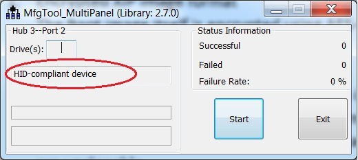
将 i.MX RT 平台连接到主机以与 i.MX RT BootROM 应用程序进行交互。平台以串行下载器模式连接后,可以使用 MfgTool 将可引导映像编程到目标闪存中。如果 cfg.ini 和 UlCfg.ini 文件都配置正确,MfgTool 会识别设备并建立连接。
下图展示了 MfgTool 已经连接。
6.3 开发过程中的程序可引导映像
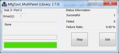
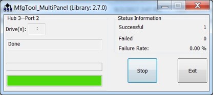
在开发阶段,对于大多数用例,设备可能处于 HAB 打开模式。用户可以将 cfg.ini 文件中的“name”字段配置为 <Device>-DevBoot,然后使用 elftosb 实用程序准备 boot_image.sb 文件。生成“boot_image.sb”后,将其放入“<Device>/OS Firmware/”文件夹。然后将设备置于串行下载器模式并将其连接到主机 PC。打开 MfgTool2.exe 并单击“Start”以触发编程序列。编程完成后,将出现下图所示的窗口。要退出 MfgTool,请点击“Stop”,然后点击“Exit”。
6.4 用于生产的程序可引导映像
在生产阶段,对于大多数用例,设备可能处于 HAB 关闭模式。用户可以将 cfg.ini 文件中的“name”字段配置为 <Device>-SecureBoot,然后使用 elftosb 实用程序准备 boot_image.sb 文件、enable_hab.sb 和 ivt_flashloader_signed.bin。全部生成后,放入“<Device>/OS Firmware/”文件夹,然后将设备置于串口下载器模式并将其连接到主机 PC。打开 MfgTool2.exe 并单击“Start”以触发编程序列。编程完成后,将看到下面的窗口。要退出 MfgTool,请点击“Stop”,然后点击“Exit”。
7 附录
7.1 插件式引导应用程序
插件式引导应用程序通常用于启用 Boot ROM 本身不支持的引导特性,例如,
- 从 U 盘引导
- 从以太网引导
- DDR/SDRAM 配置
- 冗余引导/可靠引导
插件式引导应用的原型是:
bool (*plugin_download)(void **start, size_t *bytes, uint32_t *ivt_offset);
7.1.1 插件式引导应用程序设计原则
Boot ROM 需要在插件式引导映像和插件式引导应用程序加载的普通引导映像之间跳转。为避免对 ROM 引导流程产生任何影响,以下是插件式引导应用程序设计的一些推荐原则。
- 插件式引导应用程序不能使用当前保留给 ROM 使用的内存
- 插件式引导应用程序应使用最小的栈空间以避免插件式引导应用程序导致栈溢出的可能性
- 如果 WDOG 使能位在 Fuse 块中启用,那么插件式引导应用程序必须考虑 Watchdog 服务
7.1.2 插件式引导应用程序的引导流程
插件式引导应用程序的引导流程如下:
- Boot ROM 加载 XIP 插件式引导映像,进行验证并执行,然后跳转到插件式引导应用程序
- 插件式引导应用程序从地址 0x60008000 中加载已签名的 Non-XIP 映像并跳转回 Boot ROM
- Boot ROM 根据插件式引导应用程序输出的参数进行验证/解密,验证成功后跳转到 non-XIP 引导映像
7.1.3 用于在 FlexSPI NOR 上引导 non-XIP 引导的示例插件式引导应用程序
某些 i.MX RT Boot ROM 设备本身不支持 Non-XIP 引导用例。在这种情况下,可以创建一个简单的插件式引导映像来为这些引导设备启用 non-XIP 引导用法。
插件式引导的基本流程如下:
以下是 RT10xx FlexSPI NOR 引导的插件式引导应用程序示例代码。
1 | |
7.1.4 插件式引导应用程序加载的映像
插件式引导应用程序加载的映像可以是 XIP 映像或 non-XIP 映像。有关详细信息,请参阅 4 生成 i.MX RT 可引导映像。
7.2 RT1060-EVK 的制造流程示例
7.2.1 开发阶段中的制造过程
在开发阶段,映像通常是未签名的,用于功能测试。
7.2.1.1 制造流程的模板选项
为了简化制造流程的复杂性,ucl2.xml 中提供了几个模板。
下面的代码块是用于将 SDK XIP 项目二进制文件编程到 RT1060-EVK 板中的示例。要启用 XiP 用户需要:
- 将 cfg.ini 中的“name”项更改为“name = MXRT106x-DevBootSerialFlashXiP”
- 编译 SDK 项目
- 为项目生成二进制文件
- 将二进制文件重命名为 boot_image.bin
- 将其复制到与 ucl2.xml 相同的文件夹中
1 | |
下面的代码块是用于将 SDK XIP 项目二进制文件编程到使用其他 FLASH 设备的 RT1060-EVK 板中的示例。对于实际焊接的 FLASH 设备,用户可能需要修改 0xc0000007 配置选项。有关详细信息,请参阅 MCU Flashloader Reference Manual 中的“External memory support”。
要启用该选项,用户需要:
- 将 cfg.ini 中的“name”项更改为“name = MXRT106x-DevBootSerialFlashXiP_NoConfigBlock”
- 编译 SDK 项目
- 为项目生成二进制文件
- 将二进制文件重命名为 boot_image.bin
- 将其复制到与 ucl2.xml 相同的文件夹中
1 | |
下面的代码块是用于在没有 FCB 和引导数据信息的情况下对 SDK XIP 项目二进制文件进行编程的示例。对于实际焊接的 FLASH 设备,用户可能需要修改配置选项中的 0xc0000007。有关详细信息,请参阅 MCU Flashloader Reference Manual 中的“External memory support”。
要启用该选项,用户需要:
- 将 cfg.ini 中的“name”项更改为“name = MXRT106x-DevBootSerialFlashXiP_NoConfigBlockBootData”
- 编译 SDK 项目
- 生成项目的二进制文件
- 将二进制文件重命名为 boot_image.bin
- 将其复制到与 ucl2.xml 相同的文件夹中
注:
- 对于本示例,应用程序起始地址必须为 0x60002000。
- ivt_bootdata_0x6000_2000 中的默认映像大小配置为 4 MB。它适合大多数应用程序要求。用户可以修改此文件中的偏移量 0x24-0x27 来改变映像大小以满足实际需要。
1 | |
下面的代码块是用于对存储在 FlexSPI NOR 上的 non-XIP ITCM 映像进行编程的示例。对于实际焊接的 FLASH 设备,用户可能需要修改 0xc0000007 配置选项。有关详细信息,请参阅 MCU Flashloader Reference Manual 中的“External memory support”。
要启用该选项,用户需要:
- 将 cfg.ini 中的“name”项更改为“name = MXRT106x-DevBootSerialFlashXiP_ITCM_0x0000_1400”
- 编译 SDK 项目
- 生成项目的二进制文件
- 将二进制文件重命名为 boot_image.bin
- 将其复制到与 ucl2.xml 相同的文件夹中
注:
- 此选项的应用程序起始地址必须为 0x1400。实际引导映像从地址 0x1000 开始,IVT 从偏移量 0x100 开始,应用程序从偏移量 0x1300 开始。
- ivt_bootdata_0x0000_1400 中的默认映像大小配置为 127 KB。这是因为它不能超过默认的 ITCM 大小(128 KB)。
1 | |
下面的代码块是用于对存储在 FlexSPI NOR 上的 non-XIP DTCM 映像进行编程的示例。对于实际焊接的 FLASH 设备,用户可能需要修改 0xc0000007 配置选项。有关详细信息,请参阅 MCU Flashloader Reference Manual 中的“External memory support”。
要启用该选项,用户需要:
- 将 cfg.ini 中的“name”项更改为“name = MXRT106x-DevBootSerialFlashXiP_DTCM_0x2000_2000”
- 编译 SDK 项目
- 生成项目的二进制文件
- 将二进制文件重命名为 boot_image.bin
- 将其复制到与 ucl2.xml 相同的文件夹中
注:
- 此选项的应用程序起始地址必须为 0x20002000。实际引导映像从地址 0x20000000 开始,IVT 从偏移量 0x1000 开始,应用程序从偏移量 0x2000 开始。
- ivt_bootdata_0x2000_2000 中的默认映像大小配置为 128 KB。这是因为它不能超过默认的 DTCM 大小(128 KB)。
1 | |
下面的代码块是用于对存储在 FlexSPI NOR 上的 non-XIP OCRAM 映像进行编程的示例。对于实际焊接的 FLASH 设备,用户可能需要修改 0xc0000007 配置选项。有关详细信息,请参阅 MCU Flashloader Reference Manual 中的“External memory support”。
要启用该选项,用户需要:
- 将 cfg.ini 中的“name”项更改为“name = MXRT106x-DevBootSerialFlashNonXiP_OCRAM_0x2020_a000”
- 编译 SDK 项目
- 生成项目的二进制文件
- 将二进制文件重命名为 boot_image.bin
- 将其复制到与 ucl2.xml 相同的文件夹中
注:
- 此选项的应用程序起始地址必须为 0x2020a000。实际引导映像从地址 0x20208000 开始,IVT 从偏移量 0x1000 开始,应用程序从偏移量 0x2000 开始。
- ivt_bootdata_0x2020_a000 中的默认映像大小配置为 736 KB。这是因为它不能超过默认的 OCRAM 大小(768 KB - 为 ROM 使用保留的 32 KB RAM 大小)。
1 | |
下面的代码块是用于通用目的的示例。需要创建 SB 格式的引导映像 boot_image.sb 并将其复制到与 ucl2.mxl 相同的文件夹中。创建 SB 格式引导映像的详细信息可以在第 4 章和第 5 章中找到。
1 | |
下面的代码块是在生产阶段用于通用目的的示例。需要创建 SB 格式的引导映像 boot_image.sb 并将其复制到与 ucl2.mxl 相同的文件夹中。创建 SB 格式引导映像的详细信息可以在第 4 章和第 5 章中找到。
1 | |
7.2.1.2 创建 i.MX RT 可引导映像
7.2.1.2.1 使用 KSDK XIP 示例创建映像
用户可以通过构建 KSDK XIP 项目来创建未签名的可引导映像,并将输出转换为二进制文件。需要将二进制文件重命名为 boot_image.bin 并将其复制到与 ucl2.xml 相同的文件夹中。然后用户可以更新 cfg.ini 文件以启用上一节中描述的制造流程选项。
7.2.1.2.2 使用 elftosb 实用程序创建映像
要为特定内存创建可引导映像,用户需要知道 i.MX RT106x SoC 的内存映射。生成可引导映像的详细信息可在第 4 章中找到。以下是使用 elftosb 实用程序为 FlexSPI NOR 创建 i.MX RT 可引导映像的步骤。
- 创建用于生成引导映像的 BD 文件。BD 文件内容如下所示。它也可以在“<sdk_package>/middleware/mcu-boot/bin/Tools/bd_file/imxrt10xx”的发行包中找到
1
2
3
4
5
6
7
8
9
10
11
12
13
14options {
flags = 0x00;
startAddress = 0x60000000;
ivtOffset = 0x1000;
initialLoadSize = 0x2000;
}
sources {
    elfFile = extern(0);
}
section (0)
{
} - 使用 elftosb 实用程序创建映像。
以下是示例命令:

- ivt_flexspi_nor_xip.bin
- ivt_flexspi_nor_xip_nopadding.bin
ivt_flexspi_nor_xip_nopadding.bin 将用于生成 SB 文件,以用于后续小节的 QSPI FLASH 编程。
7.2.1.2.3 创建用于 QSPI FLASH 编程的 SB 文件
这是一个为 RT1060-EVK 板的 QSPI FLASH 编程而创建的 SB 文件示例。第 5 章提供了为可引导映像编程生成 SB 文件的详细信息。
1 | |
BD 文件准备好之后,接下来就是生成 boot_image.sb 文件以供 MfgTool 使用。这是示例命令:
使用上述命令后,在 elftosb 实用程序文件夹中生成了 boot_image.sb。
7.2.2 使用 MfgTool 编程未签名映像到 Flash
使用以下步骤将引导映像编程到闪存设备中
- 将 boot_image.sb 文件复制到“<mfgtool_root_dir>/Profiles/MXRT106X/OS Firmware”文件夹。
- 将“[List]”下的“name”改为<mfgtool_root_dir>文件夹下 cfg.ini 文件中的选中选项,例如“name = MXRT106x-DevBootSerialFlashXiP”。
- 通过将 SW7 设置为“1-OFF、2-OFF、3-OFF、4-ON”,将 RT1060-EVK 板置于串行下载器模式。
- 给 RT1060-EVK 板加电,将 USB 线插入 J9。
- 打开 MfgTool,它会显示为如 Figure 19 所示的检测到的设备。
- 点击“Start”,MfgTool 将进行制造过程。完成后,将显示成功状态,如 Figure 16 所示。单击“Stop”并关闭 MfgTool。
- 将 RT1060-EVK 板置于内部引导模式并通过将 SW7 设置为“1-OFF、2-OFF、3-ON、4-OFF”来选择 QSPI FLASH 作为引导设备。然后重置设备以开始运行应用程序。
7.2.3 生产阶段的制造过程
在生产阶段,映像需要签名并且可能需要加密。在这种情况下,设备必须配置为 HAB 关闭模式。
假设 PKI 树已准备好供 cst 使用,请将“ca”、“crts”和“keys”文件夹以及 cst 可执行文件复制到包含 elftosb 实用程序可执行文件的文件夹中,如下所示:
7.2.3.1 生成签名的 i.MX RT 可引导映像
要为特定内存生成可引导映像,用户需要 i.MX RT 设备 SoC 的内存映射。4 生成 i.MX RT 可引导映像 提供了生成可引导映像的详细信息。以下是使用 elftosb 实用程序生成签名的 i.MX RT 可引导映像的步骤。
- 生成用于生成引导映像的 BD 文件。BD 文件内容如下图所示。它也可以在文件夹中的发行包中找到。
1
2
3
4
5
6
7
8
9
10
11
12
13
14
15
16
17
18
19
20
21
22
23
24
25
26
27
28
29
30
31
32
33
34
35
36
37
38
39
40
41
42
43
44
45
46
47
48
49
50
51
52
53
54
55
56
57
58
59
60
61
62
63
64
65
66
67
68
69
70
71
72
73
74
75
76
77
78
79
80
81
82
83
84
85
86options {
flags = 0x08;
startAddress = 0x60000000;
ivtOffset = 0x1000;
initialLoadSize = 0x2000;
//DCDFilePath = "dcd.bin";
# Note: This is required if the cst and elftsb are not in the same folder
//cstFolderPath = "path/CSTFolder";
# Note: This is required if the default entrypoint is not the Reset_Handler
# Please set the entryPointAddress to base address of Vector table
//entryPointAddress = 0x60002000;
}
sources {
elfFile = extern(0);
}
constants {
SEC_CSF_HEADER = 20;
SEC_CSF_INSTALL_SRK = 21;
SEC_CSF_INSTALL_CSFK = 22;
SEC_CSF_INSTALL_NOCAK = 23;
SEC_CSF_AUTHENTICATE_CSF = 24;
SEC_CSF_INSTALL_KEY = 25;
SEC_CSF_AUTHENTICATE_DATA = 26;
SEC_CSF_INSTALL_SECRET_KEY = 27;
SEC_CSF_DECRYPT_DATA = 28;
SEC_NOP = 29;
SEC_SET_MID = 30;
SEC_SET_ENGINE = 31;
SEC_INIT = 32;
SEC_UNLOCK = 33;
}
section (SEC_CSF_HEADER;
Header_Version="4.2",
Header_HashAlgorithm="sha256",
Header_Engine="DCP",
Header_EngineConfiguration=0,
Header_CertificateFormat="x509",
Header_SignatureFormat="CMS")
{
}
section (SEC_CSF_INSTALL_SRK;
InstallSRK_Table="keys/SRK_1_2_3_4_table.bin", // "valid file path"
InstallSRK_SourceIndex=0)
{
}
section (SEC_CSF_INSTALL_CSFK;
InstallCSFK_File="crts/CSF1_1_sha256_2048_65537_v3_usr_crt.pem", // "valid file path"
InstallCSFK_CertificateFormat="x509") // "x509"
{
}
section (SEC_CSF_AUTHENTICATE_CSF)
{
}
section (SEC_CSF_INSTALL_KEY;
    InstallKey_File="crts/IMG1_1_sha256_2048_65537_v3_usr_crt.pem",
    InstallKey_VerificationIndex=0, // Accepts integer or string
    InstallKey_TargetIndex=2) // Accepts integer or string
{
}
section (SEC_CSF_AUTHENTICATE_DATA;
    AuthenticateData_VerificationIndex=2,
    AuthenticateData_Engine="DCP",
    AuthenticateData_EngineConfiguration=0)
{
}
section (SEC_SET_ENGINE;
SetEngine_HashAlgorithm = "sha256", // "sha1", "Sha256", "sha512"
SetEngine_Engine = "DCP", // "ANY", "SAHARA", "RTIC", "DCP", "CAAM" and "SW"
SetEngine_EngineConfiguration = "0") // "valid engine configuration values"
{
}
section (SEC_UNLOCK;
Unlock_Engine = "SNVS, OCOTP", // "SRTC", "CAAM", SNVS and OCOTP
Unlock_features = "ZMK WRITE, SRK REVOKE")
{
} - 使用 elftosb 实用程序生成 i.MX RT 可引导映像
以下是示例命令:
在上述命令后,会生成两个可引导映像:- ivt_flexspi_nor_xip_signed.bin
- ivt_flexspi_nor_xip_signed_nopadding.bin
ivt_flexspi_nor_xip_signed_nopadding.bin 将用于生成 SB 文件以在后续小节中进行 HyperFlash 编程。
7.2.3.2 创建用于 Fuse 编程的 SB 文件
在 keys 文件夹中,有一个名为“SRK_1_2_3_4_fuse.bin”的文件。这是在引导期间用于 SRK 验证的 HASH 表。必须将其编程到 fuse 以启用安全引导模式。
下面是一个示例文件:

下面是一个示例 BD 文件,它展示了对 fuse 进行编程的过程。fuse 字段是一个 32 位长的字数据。它将由 Flashloader 以 little-endian 模式编程到 fuse 中。
1 | |
上述 BD 文件中的最后一条命令用于通过将 fuse 中的 SEC_CONFIG [1] 位设置为 1 来启用 HAB 关闭模式。
BD 文件准备好后,下一步是创建用于 Fuse 编程的 SB 文件以启用 HAB 关闭模式。
示例命令如下所示:
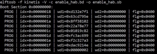
执行上图中的“enable_hab.bd -o enable_hab.sb”命令后,会生成一个名为“enable_hab.sb”的文件。MfgTool 的安全引导解决方案中需要它。
7.2.3.3 创建用于 QSPI Flash 映像加密和编程的 SB 文件
跟随着第 5 章,这里是一个生成 SB 文件的示例,其用于在 QSPIFlash 上为 MIMXRT1060-EVK 板进行映像加密和编程。
请参阅 5.1.3 生成用于 FlexSPI NOR 映像加密和编程的 SB 文件 中的 BD 文件。
BD 文件准备好之后,接下来就是生成 SB 文件了。请参阅下面的示例命令。
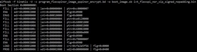
执行上图中的“program_flexspinor_image_qspinor_encrypt.bd -o boot_image.sb ivt_flexspi_nor_xip_signed_nopadding.bin”命令后,在包含 elftosb 实用程序可执行文件的文件夹中将生成一个名为“boot_image.sb”的文件。
7.2.3.4 创建签名的 Flashloader 映像
用于生成已签名的 Flashloader 映像的 BD 文件与 7.1.2.1 生成签名的 i.MX RT 可引导映像 7.2.3.1 生成签名的 i.MX RT 可引导映像 中的类似。
唯一的区别是 startAddress 是 0x20000000 和 IVTOffset 是 0x400。
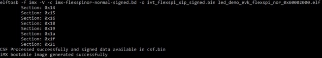
BD 文件准备好后,下一步是使用 elftosb 实用程序生成 i.MX 引导映像。示例命令如下:
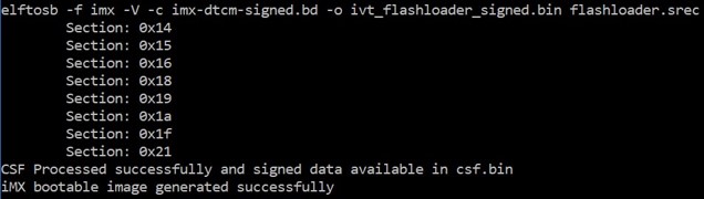
在上图中的命令“imx-dtcm-signed.bd -o ivt_flashloader_signed.bin flashloader.srec”之后,会生成两个可引导映像:
- ivt_flashloader_signed.bin
- ivt_flashloader_signed_nopadding.bin
第一个是 MfgTool 安全引导所必需的。
7.2.3.5 使用 MfgTool 将已签名映像编程到 Flash
以下是将引导映像编程到闪存设备中的步骤:
- 将 boot_image.sb 文件、ivt_flashloader_signed.bin 和 enable_hab.sb 复制到“<mfgtool_root_dir>/Profiles/MXRT106X/OS Firmware”文件夹
- 在 <mfgtool_root_dir>文件夹的 cfg.ini 文件中,将“[List]”下的“name”改为“MXRT106x-SecureBoot”
- 通过将 SW7 设置为“1-OFF、2-OFF、3-OFF、4-ON”,将 RT1060-EVK 板设置为串行下载器模式
- 给 RT1060-EVK 板上电,将 USB 线插入 J9
- 打开 MfgTool,它会显示检测到的设备。
- 点击“Start”,MfgTool 会进行制造,完成后会显示成功状态。点击“Stop”并关闭 MfgTool
- 将 RT1060-EVK 板置于内部引导模式并通过将 SW7 设置为“1-OFF、2-OFF、3-ON、4-OFF”来选择 QSPI FLASH 作为引导设备。重置设备。以太网接口上方的 LED 开始闪烁,表示映像正在运行。
7.3 手动生成 KeyBlob
在某些情况下,用户可能需要手动生成 KeyBlob。Flashloader 支持 blhost 的这种用法。
当设备在已签名的 Flashloader 应用程序的 HAB 关闭模式下工作时,必须生成 KeyBlob。
假设 dek.bin 已准备就绪(由 elftosb 实用程序在加密映像生成期间生成)。以下是生成 KeyBlob 块的示例命令。
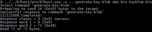
执行上图中的“blhost.exe -u –generate-key-blob dek.bin keyblob.bin”命令后,将生成一个“keyblob.bin”文件。
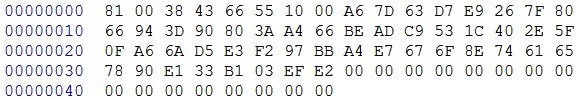
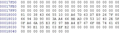
使用 Hex Editor 创建将 elftosb 实用程序生成的加密映像和 Flashloader 生成的 keyblob.bin 组合在一起以创建一个完整的加密引导映像也是可行的。在此示例中,引导映像中的 KeyBlob 偏移量为 0x18000。
下图是 Hex Editor 合成的加密映像示例。
8 修订记录
Table 19 总结了自初始版本以来对本文档所做的更改。
| Revision number | Date | Substantial changes |
|---|---|---|
| 0 | 10/2017 | Initial release |
| 1 | 05/2018 | MCU Bootloader v2.5.0 release |
| 2 | 08/2018 | RT1060 updates |
| 3 | 06/2020 | Updated Figure 7 |